File:Through-Hole Mounted Component.svg
Jump to navigation
Jump to search

Size of this PNG preview of this SVG file: 250 × 150 pixels. Other resolutions: 320 × 192 pixels | 640 × 384 pixels | 1,024 × 614 pixels | 1,280 × 768 pixels | 2,560 × 1,536 pixels.
Original file (SVG file, nominally 250 × 150 pixels, file size: 13 KB)
Captions
Captions
Add a one-line explanation of what this file represents
| Description |
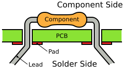
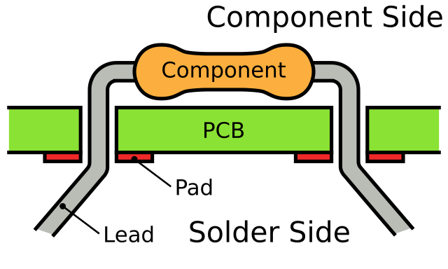
English: A diagram showing how a through-hole mounted component is inserted in to a PCB prior to soldering. Notice how the leads are bent to prevent the component falling out. |
||
| Date | |||
| Source | Own work | ||
| Author | Inductiveload | ||
| Permission (Reusing this file) |
|
||
| Other versions |
[]
|


|
This SVG file contains embedded text that can be translated into your language, using any capable SVG editor, text editor or the SVG Translate tool. For more information see: About translating SVG files. |
File history
Click on a date/time to view the file as it appeared at that time.
| Date/Time | Thumbnail | Dimensions | User | Comment | |
|---|---|---|---|---|---|
| current | 12:11, 12 July 2009 | | 250 × 150 (13 KB) | Inductiveload (talk | contribs) | {{Information |Description={{en|1=A diagram showing how a through-hole mounted component is inserted in to a PCB prior to soldering. Notice how the leads are bent to prevent the component falling out.}} |Source={{own}} |Author=[[User:Inductiveload|Inducti |
You cannot overwrite this file.
File usage on Commons
The following 4 pages use this file:
File usage on other wikis
The following other wikis use this file:
- Usage on en.wikibooks.org
- Usage on nl.wikipedia.org