Category:Digital circuits
Перайсьці да навігацыі
Перайсьці да пошуку
катэгорыя ў праектах Вікімэдыі | |||||
| Загрузіць мэдыя | |||||
| Асобны выпадак панятку | |||||
|---|---|---|---|---|---|
| |||||
Падкатэгорыі
Гэтая катэгорыя зьмяшчае наступныя 32 падкатэгорыі з 32 агулам.
A
C
- Charlieplexing (26 F)
- CORDIC (19 F)
D
E
- Digital logic equations (20 F)
F
G
- Glitch in digital electronics (36 F)
L
M
P
- Phase frequency detectors (7 F)
R
S
T
- Digital timing diagrams (16 F)
- Transmission gate (2 F)
Файлы ў катэгорыі «Digital circuits»
Паказаныя 200 файлаў гэтай катэгорыі з 230.
(папярэдняя старонка) (наступная старонка)-
 1.SOC.3.A.Gate.Combinational.20130415.pdf 1654 × 1239, 8 старонак; 62 кб
-
 1.SOC.3.A.Gate.Combinational.20160307.pdf 1654 × 1239, 12 старонак; 91 кб
-
 1.SOC.3.B.Gate.Sequential.20130415.pdf 1654 × 1239, 5 старонак; 56 кб
-
 1.SOC.3.B.Gate.Sequential.20160307.pdf 1654 × 1239, 10 старонак; 77 кб
-
 1.SOC.3.C.Gate.Subsystem.20130415.pdf 1654 × 1239, 5 старонак; 55 кб
-
 1.SOC.3.C.Gate.Subsystem.20160307.pdf 1654 × 1239, 17 старонак; 377 кб
-
 1.SOC.3.D.Gate.Delay.20130415.pdf 1654 × 1239, 13 старонак; 96 кб
-
 1.SOC.3.D.Gate.Delay.20130629.pdf 1654 × 1239, 6 старонак; 72 кб
-
 1.SOC.3.E.Gate.Power.20130415.pdf 1654 × 1239, 17 старонак; 104 кб
-
 2-pin Charlieplexing with common resistor.svg 1053 × 744; 37 кб
-
 2-pin Charlieplexing with individual resistors.svg 744 × 1053; 40 кб
-
 2BitPermutator.svg 957 × 354; 11 кб
-
 3 Pin Charlieplexing.png 440 × 266; 3 кб
-
 3-pin Charlieplexing matrix with common resistors.svg 744 × 1053; 151 кб
-
 3-pin Charlieplexing matrix with individual resistors.svg 744 × 1053; 155 кб
-
 3-pin Charlieplexing with common resistors.svg 1053 × 744; 118 кб
-
 3-pin Charlieplexing with individual resistors.svg 744 × 1053; 119 кб
-
 Ackumulator adv.png 500 × 500; 13 кб
-
 Ackumulator adv2.png 500 × 500; 13 кб
-
 Ackumulator adv3.png 500 × 500; 13 кб
-
 Ackumulator adv4.png 500 × 500; 13 кб
-
 Ackumulator simple.png 320 × 256; 5 кб
-
 Adapter BIN6.png 1145 × 404; 13 кб
-
 ADPC.png 604 × 123; 4 кб
-
 Adressregister.png 320 × 256; 3 кб
-
 Adressregister2.png 320 × 256; 4 кб
-
 Affichage4digits.png 520 × 293; 33 кб
-
 All pass interpolator.svg 1280 × 720; 12 кб
-
 AMD 22V10 Macrocell.jpg 881 × 403; 56 кб
-
 AndOrMatrixExample.svg 901 × 587; 130 кб
-
 Asynchronny citac nahor zlozeny z preklapacich obvodov D.png 1199 × 337; 12 кб
-
 AT89LV51 diagrama block.png 587 × 732; 37 кб
-
 Atmel avr rs232 resistors.JPG 597 × 274; 22 кб
-
 Autômato previsão de desvios com 2 bits para o histórico.png 400 × 266; 81 кб
-
 Band gap vs E.jpg 1000 × 750; 67 кб
-
 Bang-Bang phase detector.png 1058 × 794; 2,41 Мб
-
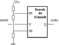 BascSchmidt.png 253 × 193; 2 кб
-
 BascSchmidt1.png 422 × 220; 2 кб
-
 Binary Booth Burk.PNG 1000 × 2000; 80 кб
-
 Binary Booth.PNG 650 × 1000; 26 кб
-
 Binary Burk.PNG 700 × 1800; 47 кб
-
 CC-Simulator.png 1291 × 997; 123 кб
-
 CDL005W.png 719 × 282; 10 кб
-
 Chase Ligh with 5 Leds.gif 611 × 333; 26 кб
-
 Chase Light with 8-Bit Shift register.gif 480 × 421; 130 кб
-
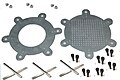 Chassis Kits.jpg 344 × 229; 24 кб
-
 Circuit de mise à 1111111...11.png 727 × 280; 10 кб
-
 Circuit de mise à zéro d'un bit.png 447 × 226; 6 кб
-
 Circuit qui effectue les opérations FHS, FFS, CLZ et autres.png 723 × 757; 16 кб
-
 Circuit sequencial.JPG 358 × 195; 8 кб
-
 Circuit value problem - animation.svg 200 × 350; 3 кб
-
 Circuit.svg 497 × 179; 35 кб
-
 Circuito elettrico.png 800 × 588; 187 кб
-
 Circuito verifica porta AND.png 672 × 344; 45 кб
-
 Circuito.png 450 × 170; 8 кб
-
 Clock on demand.png 1158 × 900; 80 кб
-
 Cmosbuff.png 852 × 669; 78 кб
-
 Combinational logic.GIF 264 × 336; 4 кб
-
 Combinatorial Logic Example.svg 452 × 182; 38 кб
-
 Common input of IEC functional block.svg 531 × 354; 6 кб
-
 Conditional Capture.png 830 × 860; 45 кб
-
 Conditional precharge.png 646 × 886; 39 кб
-
 CPU adv.PNG 1000 × 1500; 77 кб
-
 CPU adv2.PNG 1000 × 1500; 77 кб
-
 CPU AND.PNG 450 × 250; 7 кб
-
 CPU D VIPPA.PNG 320 × 256; 3 кб
-
 CPU IR4 1.PNG 900 × 7150; 409 кб
-
 CPU IR5 1.PNG 900 × 8150; 447 кб
-
 CPU IR6 1.PNG 900 × 7700; 439 кб
-
 CPU JK VIPPA.PNG 320 × 256; 4 кб
-
 CPU Mnemonics 2.PNG 500 × 800; 35 кб
-
 CPU Mnemonics 3.PNG 500 × 800; 38 кб
-
 CPU PC.PNG 800 × 600; 19 кб
-
 CPU PC2.PNG 800 × 600; 20 кб
-
 CPU SR VIPPA.PNG 320 × 256; 3 кб
-
 CPU SR.PNG 800 × 600; 17 кб
-
 CPU T VIPPA.PNG 320 × 256; 4 кб
-
 CPU testrigg.PNG 1500 × 1100; 75 кб
-
 CPU timing4.PNG 300 × 256; 6 кб
-
 CPU Transistor.PNG 300 × 250; 3 кб
-
 CpucrPinout.png 715 × 509; 20 кб
-
 Crossover nand svg.svg 478 × 230; 38 кб
-
 Crossover nand.pdf 795 × 383; 22 кб
-
 Crossover xor.gif 633 × 644; 4 кб
-
 CurrentSwitchLogic.svg 1052 × 744; 132 кб
-
 CyOut MUX2s.png 756 × 443; 7 кб
-
 D-триггер с динамическим тактированием.PNG 308 × 457; 12 кб
-
 Data Transition Look Ahead.png 1348 × 854; 87 кб
-
 Dataregister.png 320 × 256; 4 кб
-
 Dataregister2.png 320 × 256; 5 кб
-
 Dataregister4.png 330 × 256; 6 кб
-
 DCC Decoder.jpg 640 × 480; 115 кб
-
 Dds frequency-8 14.svg 512 × 384; 16 кб
-
 Dds.svg 653 × 248; 19 кб
-
 Detector de flanco de bajada.JPG 512 × 384; 21 кб
-
 Diagrama bloc.jpg 777 × 841; 113 кб
-
 Digital buffer.svg 354 × 177; 2 кб
-
 Digital clock.png 822 × 505; 39 кб
-
 Diode logic for transistor clock.jpg 1632 × 2564; 526 кб
-
 Direct digital synthesizer block diagram.png 539 × 280; 11 кб
-
 DPCM irudi 1.png 589 × 270; 13 кб
-
 DPCM laginaren aurreikuspena.png 528 × 336; 14 кб
-
 Dpcm sistesi bidezko azterketa.png 487 × 386; 12 кб
-
 DZTL.png 320 × 256; 4 кб
-
 ECC NASA standard coder.svg 842 × 595; 9 кб
-
 ECL.svg 851 × 661; 55 кб
-
 Enand gate.svg 1390 × 409; 6 кб
-
 Entprellte Taste.svg 628 × 603; 11 кб
-
 Entradas possíveis.jpg 2451 × 340; 99 кб
-
 Es1 Sistemi01.JPG 1058 × 488; 42 кб
-
 Es1 Sistemi02.JPG 586 × 504; 30 кб
-
 Example circuitry.jpg 467 × 982; 86 кб
-
 Exor and FF comparator for NRZ data.png 982 × 600; 47 кб
-
 Exor phase comparator of clocks.png 1123 × 794; 2,55 Мб
-
 FA FS.PNG 650 × 550; 14 кб
-
 Foto circuito.jpg 1310 × 733; 209 кб
-
 Ground Bounce.svg 450 × 375; 28 кб
-
 Ground loop - balanced line.svg 949 × 514; 54 кб
-
 Ground loop - common impedance coupling.svg 944 × 517; 46 кб
-
 Ground loop - electromagnetic fields.svg 958 × 576; 51 кб
-
 Ground loop - ground lift.svg 1100 × 510; 50 кб
-
 Ground loop - isolation transformer.svg 961 × 534; 31 кб
-
 Ground loop - leakage currents simplified.svg 1275 × 523; 43 кб
-
 Ground loop - parasitic elements.svg 940 × 569; 45 кб
-
 Ground loop - signal circuitry fixed.svg 1120 × 516; 63 кб
-
 Ground loop - signal circuitry raw.svg 1120 × 516; 62 кб
-
 HCMOS-spike.png 512 × 349; 8 кб
-
 Huge circuit.JPG 2592 × 1944; 855 кб
-
 I2L-architecture.PNG 320 × 256; 6 кб
-
 IEC compound functional block.svg 248 × 319; 3 кб
-
 IEC output AND dependence ratio.svg 744 × 283; 4 кб
-
 IEC standard logic symbol.svg 744 × 283; 4 кб
-
 IEC terminal inversion symbol.svg 319 × 142; 1 кб
-
 Inverseur commandable.png 727 × 280; 9 кб
-
 K145IK17 Russian pong style ICs.jpg 320 × 178; 27 кб
-
 KOI Att ctrl 2.PNG 650 × 1100; 29 кб
-
 KOL Grid Data 2.PNG 800 × 500; 13 кб
-
 KOL Lines Enabled.PNG 1000 × 500; 22 кб
-
 KOL Sampling Swap 2.PNG 700 × 900; 27 кб
-
 KOL Sampling Swap.PNG 700 × 900; 29 кб
-
 KOL Spartan 2.PNG 1200 × 1350; 67 кб
-
 KOL Spartan 3.PNG 1200 × 1400; 69 кб
-
 KOL Ts Enable 4.PNG 900 × 500; 18 кб
-
 KOL Ts Tswap Address 2.PNG 900 × 700; 27 кб
-
 KOL Ts Tswap Address 3.PNG 900 × 700; 25 кб
-
 KOL Tsw Generator 2.PNG 1500 × 1000; 47 кб
-
 KOL Tsw Generator.PNG 1300 × 1000; 43 кб
-
 KOL TV Read (adr+sim.data) 2.PNG 900 × 800; 27 кб
-
 KOL TV Read (adr+sim.data).PNG 1200 × 800; 37 кб
-
 KOL TV Read Clock.PNG 1000 × 500; 21 кб
-
 Linear interpolator.svg 1280 × 720; 9 кб
-
 Linear phase comparator for NRZ data input var gain.png 1042 × 577; 52 кб
-
 Listdesberdintasunak.png 1128 × 531; 339 кб
-
 Logic block2.svg 275 × 75; 12 кб
-
 Logic Nikolay.PNG 315 × 688; 12 кб
-
 MainVHDL.jpg 999 × 749; 60 кб
-
 Maskin simpel.png 320 × 256; 4 кб
-
 Maskin simpel2.png 320 × 256; 4 кб
-
 Maskin simpel3.png 320 × 256; 5 кб
-
 Maskin simpel4.png 550 × 450; 19 кб
-
 Maskin simpel5.png 550 × 450; 19 кб
-
 Maskin simpel6.png 700 × 600; 31 кб
-
 Measure Delay of an Not Scope 1.svg 156 × 120; 12 кб
-
 Measure Delay of an Not Scope 2.svg 156 × 120; 11 кб
-
 Mfrey Develop Digital Circuit 000 Colored.svg 455 × 410; 24 кб
-
 Mfrey Develop Digital Circuit 000.svg 455 × 410; 24 кб
-
 Mfrey Develop Digital Circuit 001.svg 455 × 410; 22 кб
-
 Mfrey Develop Digital Circuit 002.svg 455 × 410; 17 кб
-
 Mfrey Develop Digital Circuit 003.svg 455 × 410; 13 кб
-
 Mfrey Develop Digital Circuit 004.svg 455 × 410; 9 кб
-
 Mfrey Develop Digital Circuit 005.svg 455 × 410; 5 кб
-
 Mfrey Develop Digital Circuit 100.svg 560 × 500; 28 кб
-
 Mfrey Develop Digital Circuit 101.svg 560 × 500; 28 кб
-
 MFrey Infrared Remote Controll Tester Img1.jpg 1600 × 1200; 178 кб
-
 MFrey Infrared Remote Controll Tester Img2.jpg 1600 × 1200; 181 кб
-
 MFrey Infrared Remote Controll Tester Img3.jpg 1600 × 1200; 195 кб
-
 MFrey Infrared Remote Controll Tester Img4.jpg 1600 × 1200; 232 кб
-
 Mfrey remote controller tester parts.jpg 1600 × 1200; 412 кб
-
 MFrey TTL Output.svg 240 × 560; 8 кб
-
 Modulator - first order - accumulator - lowpass.svg 765 × 180; 19 кб
-
 Modulator - first order - digital.svg 540 × 180; 18 кб
-
 Modulator - first order - FF.svg 585 × 180; 14 кб
-
 Modulator - first order - integrator - lowpass.svg 765 × 180; 16 кб
-
 Modulator - second order - digital.svg 743 × 225; 28 кб
-
 MUL DIV.PNG 900 × 1400; 47 кб
-
 Omkodare2.png 320 × 500; 9 кб
-
 OP-realisering.png 750 × 900; 37 кб
-
 OverbeckCounter2.png 642 × 282; 11 кб
-
 PALASM Design.jpg 552 × 674; 75 кб
-
 PALSolution1.png 420 × 151; 10 кб
-
 PCM euskaraz.png 368 × 195; 7 кб
-
 Por3.png 320 × 256; 3 кб
-
 PRINT 06.TIF 512 × 349; 23 кб
-
 Propositional formula flip flops 1.png 748 × 782; 193 кб
-
 Propositional formula NANDs.png 928 × 800; 236 кб
-
 Propositional formula oscillator 1.png 1252 × 602; 169 кб
-
 Prototyping board.jpg 600 × 508; 70 кб
-
 Ps2 2octets.png 529 × 408; 56 кб
-
 Ps2 Horloge Compt.png 551 × 201; 30 кб
-
 Register transfer level - example toggler.svg 300 × 200; 8 кб


_2.PNG)
.PNG)


