File:Loose coupler 1919.jpg
Loose_coupler_1919.jpg (519 × 274 pixels, file size: 28 KB, MIME type: image/jpeg)
Captions
Captions
Summary[edit]
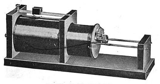
| Description |
English: A "loose coupler" tuning transformer for an early crystal radio receiver around 1920. This was attached to the antenna and the crystal detector and served as a tuned circuit bandpass filter to allow the frequency of the desired radio station through but reject signals at all other frequencies. It consisted of two coils of fine wire. The primary coil (right) was stationary, while the smaller secondary could be slid in or out of the primary on a rack. The primary was connected to the radio's wire antenna and ground, while the secondary was connected to the crystal detector. Both coils functioned as tuned circuits; the secondary resonated with a capacitor connected across its windings, while the primary resonated with the capacitance of the antenna. Different stations were tuned in by sliding the metal contact (top left) along the primary, which allowed more or fewer turns into circuit, varying the inductance and therefore the resonant frequency of the primary. The secondary was tuned by the taps selected by the multiposition switch on the end of the coil. The sliding coil was used to vary the magnetic coupling (mutual inductance) between the two coils, to adjust the bandwidth of the receiver. A serious problem with these early radio receivers was that the simple tuned circuit was not very selective; it allowed through a broad band of frequencies, so often two stations were heard in the earphones. Unlike in an ordinary transformer, in the loose coupler the two coils were "loosely coupled" so not all the magnetic field from the primary passed through the secondary. This gave the two coupled tuned circuits a much narrower bandwidth. When a nearby station interfered with reception, the secondary coil was slid further out of the primary, which reduced the mutual inductance, reducing the bandwidth, rejecting the interfering signal. |
| Date | |
| Source | Retrieved January 6, 2016 from Cyril Methodius Jansky (1919) Principles of Radiotelegraphy, McGraw-Hill Book Co., New York, p. 211, fig. 149 on Google Books |
| Author | Cyril Methodius Jansky |
Licensing[edit]
This media file is in the public domain in the United States. This applies to U.S. works where the copyright has expired, often because its first publication occurred prior to January 1, 1929, and if not then due to lack of notice or renewal. See this page for further explanation.
|
 | |
 |
This image might not be in the public domain outside of the United States; this especially applies in the countries and areas that do not apply the rule of the shorter term for US works, such as Canada, Mainland China (not Hong Kong or Macao), Germany, Mexico, and Switzerland. The creator and year of publication are essential information and must be provided. See Wikipedia:Public domain and Wikipedia:Copyrights for more details.
|
File history
Click on a date/time to view the file as it appeared at that time.
| Date/Time | Thumbnail | Dimensions | User | Comment | |
|---|---|---|---|---|---|
| current | 09:30, 6 January 2016 | | 519 × 274 (28 KB) | Chetvorno (talk | contribs) | User created page with UploadWizard |
You cannot overwrite this file.
File usage on Commons
There are no pages that use this file.