File:Taylor hydraulic air compressor at Magog.png

Original file (1,210 × 2,354 pixels, file size: 1.57 MB, MIME type: image/png)
Captions
Captions
Summary[edit]
| Description |
Français : Trompe à eau conçue par Charles Havelock Taylor (1859-1953) et utilisée à Magog, au Québec.
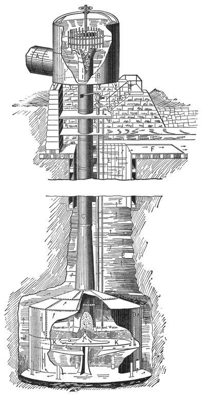
English: Tromp designed by Charles Havelock Taylor (1859-1953) and used at Magog, Quebec.
It is a modification of the ancient "trompe," or water blast, used for centuries to feed the forges of Catalonia, very simple in operation and cheap to build. In its present improved form it is known as the Taylor Hydraulic Air Compressor, and an initial plant of very respectable size has been in highly successful operation for some five years past at Magog, P. Q., from which the data here given have been obtained. The compressing apparatus which is shown in Fig. 21 is in principle an inverted siphon having near its upper end a series of intake tubes for air, and at the bend a chamber to collect the air which, entrained in the form of fine bubbles, is carried down with the water column, which flowing up the short arm of the siphon escapes into the tail race. In Fig. 21, A is the penstock delivering water to the supply tank B. In this tank is the mouth of the down tube C, contracted by the inverted cone C so as to lower the hydraulic pressure and allow ready access of air from the surrounding apertures. The air bubbles trapped in the water sweep down C, which expands at the lower end, and finally enters the air tank D. Here the water column encounters the cone K, which flattens into a plate at the base. Thus spread out and escaping into the air chamber by the circuitous route shown by the arrows, the air bubbles from the water accumulate in the top of the air tank, while the water itself rises up the shaft E, and flows into the tail race F. The air in D is evidently under a pressure due to the height of the water column up to F, and quite independent of the fall itself, which consequently may vary greatly without affecting the pressure of the stored air, a very valuable property in some cases, as in utilizing tidal falls. From D the compressed air is led up through a pipe, P, for distribution to the motors. To get more pressure, it is only necessary to burrow deeper with the air tank, not a difficult task where easy digging can be found. The fall and rate of flow determine the rate at which the air is compressed, and contrary to what might be supposed, the process of compression is quite efficient. It is quite sensitive to variations in the amount of flow, the efficiency changing rapidly with the conditions of inlet; and since there certainly is a limit to the amount of air that can be entrained in a given volume of water, the process is likely to work most efficiently at moderate heads and with large volumes of water. In the Magog compressor about 4 cubic feet of water are required to entrain 1 cubic foot of air at atmospheric pressure, and it is open to question as to how far this ratio could be improved. This ratio, too, would be changed for the worse rapidly in attempting high compression, so that the Magog results probably represent, save for details, very good working conditions. The dimensions of the Magog apparatus are given in the accompanying table, which is followed by the details of one of the tests made by a very competent body of engineers. The general dimensions of the compressor plant are: Supply penstock 60 inches diameter Supply tank at top 8 feet diameter by 10 feet high Air inlets (feeding numerous small tubes) 34 2-inch pipes Down tube 44 inches diameter Down tube at lower end 60 inches diameter Length of taper in down tube, changing from 44-inch to 60-inch diameter 20 feet Air chamber in lower end of shaft 16 feet diameter Total depth of shaft below normal level of head water about 150 feet Normal head and fall about 22 feet Air discharge pipe 7 inches diameter Flow of water, cubic feet, minute 4292. Head and fall in feet 19.509 Gross water HP 158.1 Cubic feet compressed air per minute, reduced to atmospheric pressure 1148. Pressure of compressed air, Ibs 53.3 Pressure of atmosphere, Ibs 14.41 Effective work done in compressing air, HP 111.7 Efficiency of the compressor, per cent 70.7 Temperature of external air, Fahr 65.2 Temperature of water and compressed air, Fahr 66.5 Moisture in air entering compressor, per cent of saturation . 68. Moisture in air after compression, per cent of saturation 35. The efficiency given is certainly most satisfactory, being quite as high as could be attained by a compound compressor of the best construction driven by a turbine, and for the head in question at a very much lower cost. It is probable that the test given does not represent the best that can be done by this method, and the indications are that within a certain, probably somewhat limited, range of heads the hydraulic compressor will give as compressed air a larger proportion of the energy of the water than any other known apparatus. Just what its limitations are, remains to be discovered, but several plants are now under construction which will throw considerable light upon the subject. |
| Date | |
| Source | Electric power transmission; a practical treatise for practical men p. 56 |
| Author | Louis Bell (1864-1923) |
Licensing[edit]
|
This work is in the public domain in its country of origin and other countries and areas where the copyright term is the author's life plus 70 years or fewer. This work is in the public domain in the United States because it was published (or registered with the U.S. Copyright Office) before January 1, 1929. | |
| This file has been identified as being free of known restrictions under copyright law, including all related and neighboring rights. | |
File history
Click on a date/time to view the file as it appeared at that time.
| Date/Time | Thumbnail | Dimensions | User | Comment | |
|---|---|---|---|---|---|
| current | 21:30, 18 January 2018 | | 1,210 × 2,354 (1.57 MB) | Borvan53 (talk | contribs) | User created page with UploadWizard |
You cannot overwrite this file.
File usage on Commons
There are no pages that use this file.
File usage on other wikis
The following other wikis use this file:
- Usage on fr.wikipedia.org