Category:Electrical circuits
Salti al navigilo
Salti al serĉilo

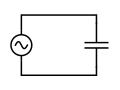
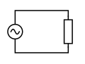
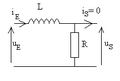
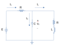
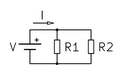
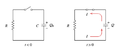
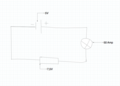
interconnection of electrical components or a model of such an interconnection, consisting of electrical elements  Circuit diagram describing a simple electrical network | |||||
| Alŝuti plurmedion | |||||
| Subaro de |
| ||||
|---|---|---|---|---|---|
| Parto de | |||||
| Havas parton |
| ||||
| Alia ol | |||||
| |||||
Subkategorioj
Ĉi tiu kategorio havas la 29 jenajn subkategoriojn, el 29 entute.
*
A
- AC network diagrams (25 D)
- Aron circuit (11 D)
B
C
D
F
- Fuse circuits (5 D)
H
I
K
L
M
- Mesh analysis (25 D)
N
O
R
S
- SVG electrical circuits (116 D)
T
V
- Voltage doubler (28 D)
W
- Wye-Delta transform (36 D)
Dosieroj en kategorio “Electrical circuits”
La jenaj 200 dosieroj estas en ĉi tiu kategorio, el 533 entute.
(antaŭa paĝo) (sekva paĝo)-
 $Kill - Legado.jpg 2 048 × 1 152; 430 KB
-
 0416999-2c.JPG 1 936 × 2 592; 2,38 MB
-
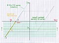
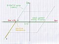
 100Hz-negative-group-delay-wave-1Ghz-bandwidth-opamp.png 1 145 × 668; 20 KB
-
 12ph wbg.gif 260 × 230; 3 KB
-
 13йцуке.JPG 197 × 222; 7 KB
-
 1б.png 328 × 193; 17 KB
-
 2014 FCC Technician-Class Exam Study Guide T2.jpg 1 800 × 1 200; 137 KB
-
 2014 FCC Technician-Class Exam Study Guide T3.jpg 1 800 × 1 200; 106 KB
-
 2020-Hidden-Chua-attractors-Circuit-realization.jpg 4 000 × 3 000; 6,34 MB
-
 3generators1resistance.png 543 × 291; 8 KB
-
 8-1 Decoder Circuit.jpg 960 × 1 280; 282 KB
-
 A paper circuit I did.jpg 4 032 × 3 024; 3,23 MB
-
 A weakly circuit.PNG 416 × 148; 7 KB
-
 A weakly nonlinear circuit.PNG 416 × 148; 7 KB
-
 Ac-capacitor-circuit.svg 151 × 113; 2 KB
-
 Ac-resistor-circuit.svg 151 × 113; 2 KB
-
 An example of a basic circuit..jpg 462 × 395; 17 KB
-
 ANALABY4 Analogschaltung Labyrinth.PNG 272 × 271; 5 KB
-
 Analoger Pegelumsetzer Neu.png 350 × 220; 8 KB
-
 Análise de circuitos.jpg 3 888 × 2 592; 1,98 MB
-
 ARC CB.JPG 475 × 380; 33 KB
-
 Arc suppression circuit.png 1 010 × 668; 167 KB
-
 Association R C parallèle en série avec L en r.s.f. - bis.png 299 × 143; 1 KB
-
 Association R C parallèle en série avec L en r.s.f.png 310 × 185; 3 KB
-
 Association R L parallèle en série avec C en r.s.f. - bis.png 255 × 214; 3 KB
-
 Association R L parallèle en série avec C en r.s.f.png 246 × 216; 2 KB
-
 Audio Output Stage (2843241676).jpg 700 × 294; 25 KB
-
 AufbauCASSY.jpg 1 318 × 1 591; 230 KB
-
 Auto-induction - influence bobine sur i fonction de t.png 368 × 178; 13 KB
-
 Avalanche bjt base trigger.png 307 × 300; 15 KB
-
 Avalanche bjt collector trigger.png 196 × 300; 17 KB
-
 BAC 2003 Antilles PC EX3 FIG1.png 1 219 × 496; 29 KB
-
 Balanced amplifier topology.svg 652 × 688; 13 KB
-
 Banc d'essai sonar.jpg 3 222 × 2 428; 1,9 MB
-
 Bandpass FSS.jpg 960 × 720; 17 KB
-
 Bandstop.jpg 960 × 720; 15 KB
-
 Baterias 4.5V D C AA AAA AAAA A23 9V CR2032 LR44.jpg 3 629 × 1 076; 1,04 MB
-
 BatteriaLampadaInterrutoreAcceso.png 663 × 518; 356 KB
-
 BatteriaLampadaInterrutoreSpento.png 712 × 520; 350 KB
-
 Bildleistung kompensiert.svg 384 × 167; 63 KB
-
 Bistable inic 2a 1000.jpg 1 000 × 733; 95 KB
-
 Bistable inic 3a 1000.jpg 1 000 × 742; 95 KB
-
 Bistable inic 4a 1000.jpg 1 000 × 737; 96 KB
-
 Blindleistung unkompensiert.svg 384 × 167; 36 KB
-
 Boost and Drive relays mounted on PC board.jpg 1 034 × 768; 928 KB
-
 Brockhaus and Efron Encyclopedic Dictionary b15 023-0.jpg 594 × 613; 33 KB
-
 Brune Test Parallel Parallel.png 4 200 × 3 000; 262 KB
-
 Brune Test Series-Parallel.png 4 200 × 3 000; 259 KB
-
 Brune Test Series-Series Fail.png 2 419 × 1 650; 156 KB
-
 Brune Test Series-Series Pass Xfmr.png 2 588 × 1 650; 182 KB
-
 Brune Test Series-Series Pass.png 2 419 × 1 650; 150 KB
-
 Brune Test Series-Series.png 4 200 × 3 000; 256 KB
-
 Capturesss.png 623 × 351; 85 KB
-
 Carga e descarga de um condensador..png 357 × 162; 5 KB
-
 Cascode (triode).svg 512 × 723; 22 KB
-
 Cell model new.png 564 × 299; 31 KB
-
 Charlieplexing pattern.png 289 × 250; 14 KB
-
 Chopper circuit.png 436 × 436; 294 KB
-
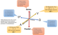
 Circtuito-serie-paralelo-cortocircuito-01.png 1 663 × 703; 13 KB
-
 Circtuito-serie-paralelo-cortocircuito-02.png 1 663 × 703; 13 KB
-
 Circtuito-serie-paralelo-cortocircuito-03.png 1 663 × 703; 14 KB
-
 Circtuito-serie-paralelo-cortocircuito-04.png 1 663 × 703; 14 KB
-
 Circtuito-serie-paralelo-cortocircuito-05.png 1 663 × 703; 14 KB
-
 Circtuito-serie-paralelo-cortocircuito-06.png 1 663 × 703; 13 KB
-
 Circuit 1.png 448 × 225; 16 KB
-
 Circuit 4.png 883 × 546; 49 KB
-
 Circuit diagram 1.JPG 2 578 × 1 534; 1,19 MB
-

-

-
-

-

-
-

-
-

-
-

-

-
-

-

-

-
-

-
-

-
 Circuit equivalence.png 1 748 × 2 225; 18 KB
-

-
 Circuit L R série - sortie ouverte aux bornes de R.png 213 × 143; 1 019 bajtoj
-
 Circuit R C série - sortie aux bornes de C - bis.png 263 × 172; 3 KB
-
 Circuit R C série - sortie aux bornes de C.png 173 × 172; 2 KB
-
 Circuit Symbols for A-level-OCR-Physics A.png 1 164 × 427; 44 KB
-
 Circuit Symbols.JPG 2 448 × 3 264; 2,6 MB
-
 Circuit with resistors and pots.JPG 2 592 × 1 936; 2,04 MB
-
 Circuit à deux cellules RC en r.s.f.png 243 × 161; 3 KB
-
 Circuit-Box.jpg 1 024 × 768; 52 KB
-
 Circuit.png 1 502 × 753; 16 KB
-
 Circuit2.png 1 502 × 753; 18 KB
-
 Circuit3.png 1 502 × 753; 22 KB
-
 CircuitElectriqueEtHydraulique.png 1 043 × 428; 29 KB
-
 Circuito com duas malhas..png 382 × 167; 8 KB
-
 Circuito del secondo ordine.png 536 × 406; 12 KB
-
 Circuito elettrico lineare.png 536 × 380; 13 KB
-
 Circuito eléctrico.png 1 858 × 2 887; 75 KB
-

-
 Circuito exemplo - Transformada de Fourier.jpg 521 × 317; 19 KB
-
 Circuito impreso A recorte.JPG 942 × 884; 325 KB
-
 Circuito LC.png 481 × 194; 8 KB
-
 Circuito no dominio tempo - Exemplo I.jpg 816 × 127; 42 KB
-
 Circuito no dominio tempo - Exemplo.jpg 816 × 127; 45 KB
-
 Circuito no dominio tempo.jpg 786 × 127; 28 KB
-
 Circuito resistivo adattato.png 425 × 267; 6 KB
-
 Circuito senza generatore di ccorrente.png 362 × 155; 2 KB
-
 Circuito thevenin.png 455 × 272; 9 KB
-
 Circuito Tradicional.JPG 256 × 128; 7 KB
-
 Circuito-electrico-mixto.png 1 175 × 780; 14 KB
-
 Circuito-electrico-paralelo-simplificado.png 2 528 × 680; 25 KB
-
 Circuito-electrico-paralelo.png 1 176 × 780; 11 KB
-
 Circuito-electrico-serie-simplificado.png 2 099 × 780; 21 KB
-
 Circuito-electrico-serie.png 845 × 780; 11 KB
-
 Circuito-electrico.png 780 × 780; 7 KB
-
 CIRCUITO.jpg 845 × 398; 36 KB
-
 Circuito00.png 914 × 572; 10 KB
-
 Circuitoelectroiman.jpg 705 × 227; 33 KB
-
 CircuitoRettificatore.png 400 × 245; 6 KB
-
 Circuitos Elétricos, Métodos de Análise e Introdução à Síntese.pdf 1 239 × 1 752, 461 paĝoj; 5,92 MB
-
 Circuitoscorrientedirecta2.jpg 536 × 326; 22 KB
-
 CircuitosZ.jpg 438 × 169; 19 KB
-
 CircuitSAT.svg 460 × 120; 4 KB
-
 Classical-APLL-phases.jpg 807 × 528; 60 KB
-
 Classical-APLL-signals.jpg 1 679 × 274; 66 KB
-
 ComplexDCCircuitKirchhoffLaw.svg 2 041 × 2 296; 46 KB
-
 Condensatori su due rami.png 960 × 720; 8 KB
-
 Conv52.jpg 750 × 410; 47 KB
-
 CP-PLL.pdf 1 187 × 389; 235 KB
-
 Cuadd1.PNG 448 × 994; 21 KB
-
 Cuadd2.PNG 710 × 771; 19 KB
-
 Current Division.svg 588 × 251; 34 KB
-
 Current sensing current injecting.png 907 × 314; 22 KB
-
 Current sensing voltage injecting.png 905 × 343; 18 KB
-
 CurrentSource Capacitor Circuit.JPG 210 × 98; 3 KB
-
 DC circuit setup.jpg 2 992 × 4 000; 4,59 MB
-
 Defibrilator circuit.jpg 3 899 × 2 123; 3,24 MB
-
 Depictions of bridge topology.svg 1 999 × 880; 24 KB
-
 Derevenets mew Средн точка график.gif 479 × 265; 5 KB
-
 Derevenets mew Средн точка.gif 315 × 267; 3 KB
-
 Derevenets Мост схема.gif 366 × 167; 3 KB
-
 Derevenets Полумост схема.jpg 360 × 169; 17 KB
-
 Derevenets Средн точка график.gif 479 × 299; 5 KB
-
 Derevenets Средн точка.gif 315 × 267; 3 KB
-
 Descarga de um condensador..png 414 × 174; 6 KB
-
 Desenho auxiliar - SEPIC.svg 990 × 312; 57 KB
-

-
 Dianlutu.jpeg 1 001 × 1 334; 112 KB
-
 Dianlutu2.jpeg 1 001 × 1 334; 115 KB
-
 Divisor de Corrente.png 1 088 × 486; 13 KB
-
 DMCMsijais.png 451 × 638; 16 KB
-
 Donald Betsy Gillies Illiac I.jpg 1 712 × 1 178; 707 KB
-
 Duality in electrical circuit.png 3 033 × 1 823; 228 KB
-
 Electric circuit.jpg 1 025 × 744; 70 KB
-
 Electric locomotive haulage in and about mines (1913) (14778124273).jpg 2 198 × 1 256; 334 KB
-
 Electric source and load animation 2.gif 510 × 313; 95 KB
-
 Electric source and load animation.gif 510 × 313; 118 KB
-
 Electric-symbol-alternator.png 166 × 80; 3 KB
-
 Electric-symbol-ampmeter.png 166 × 79; 3 KB
-
 Electric-symbol-battery.png 166 × 79; 950 bajtoj
-
 Electric-symbol-buzzer.png 166 × 79; 1 KB
-
 Electric-symbol-coil.png 168 × 79; 3 KB
-
 Electric-symbol-electromagnet.png 166 × 79; 2 KB
-
 Electric-symbol-junction.png 166 × 79; 873 bajtoj
-
 Electric-symbol-light-bulb.png 166 × 80; 3 KB
-
 Electric-symbol-motor.png 166 × 79; 2 KB
-
 Electric-symbol-pushbutton-nc.png 166 × 79; 1 KB
-
 Electric-symbol-pushbutton-no.png 166 × 79; 1 KB
-
 Electric-symbol-resistor.png 166 × 79; 763 bajtoj
-
 Electric-symbol-switch-st-limit.png 166 × 79; 3 KB
-
 Electric-symbol-switch-st.png 166 × 79; 1 KB
-
 Electric-symbol-voltmeter.png 166 × 79; 3 KB
-
 Electrical circuit demonstration closeup.jpg 3 024 × 4 032; 2,47 MB
-
 Electrical circuit.jpg 3 264 × 2 448; 3,25 MB
-
 Electricidad-circuito-simbolos-01.png 434 × 307; 4 KB
-
 Electricidad-circuito-simbolos-02.png 448 × 357; 5 KB
-
 Electronics Coursework.JPG 2 560 × 1 920; 1,02 MB
-
 Elektický obvod.png 1 280 × 720; 5 KB
-
 Elektrische Modellierung eines Wälzlagers.png 815 × 874; 84 KB
-
 Elektriskeem RVP-ks.jpg 909 × 683; 42 KB
-
 Elkrets med resistor och lampa.png 772 × 556; 49 KB
-

-
 EMF of a turn saturated ferromagnetic core.png 1 869 × 1 600; 47 KB
-
 Energetic 1000.jpg 1 000 × 701; 64 KB
-
 Energetiic 1000.jpg 1 000 × 701; 53 KB
-
 Equivalent-Circuit-R C-S P connection.svg 512 × 473; 20 KB
-
 Esquema de control.PNG 214 × 582; 6 KB
-
 Esquema de potencia.PNG 226 × 266; 2 KB
-
 Esquema neumático.PNG 261 × 495; 5 KB
-
 EsquemaEletricoSimples.png 238 × 170; 3 KB
-
 Ett kopplingsshema.png 248 × 201; 11 KB
-
 Everding-HKZ ESB.png 680 × 900; 11 KB
-
 Exemplo I - Circuito - Função de transferência.jpg 816 × 127; 49 KB


.jpg)


.svg)


.png)
.png)

.png)
.png)

.png)
.png)


.png)

.png)


_(14778124273).jpg)


