File:Common crystal radio circuit.svg
维基共享资源,媒体文件资料库
跳转到导航
跳转到搜索

此SVG文件的PNG预览的大小:517 × 426像素。 其他分辨率:291 × 240像素 | 583 × 480像素 | 932 × 768像素 | 1,243 × 1,024像素 | 2,486 × 2,048像素。
原始文件 (SVG文件,尺寸为517 × 426像素,文件大小:23 KB)
文件信息
结构化数据
说明
说明
添加一行文字以描述该文件所表现的内容
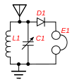
A circuit diagram of a crystal radio
摘要
[编辑]| 描述Common crystal radio circuit.svg |
English: Common crystal radio circuit, used in inexpensive crystal radios sold today. The tuning coil L and capacitor C1 together make up the tuned circuit; it selects the radio signal to be received, out of all the signals picked up by the antenna. C1 is adjustable, and is used to tune in different stations. The crystal detector D rectifies the radio frequency current from the tuned circuit to pulsing direct current to extract the audio modulation from the radio frequency carrier wave. The earphone E converts the audio current to sound waves. |
| 日期 | |
| 来源 | 自己的作品 |
| 作者 | Chetvorno |
| SVG开发 InfoField | 本矢量图使用Adobe Illustrator创作。 |
许可协议
[编辑]| Public domainPublic domainfalsefalse |
| 本作品已被作者Chetvorno释出到公有领域。这适用于全世界。 在一些国家这可能不合法;如果是这样的话,那么: Chetvorno无条件地授予任何人以任何目的使用本作品的权利,除非这些条件是法律规定所必需的。 |
文件历史
点击某个日期/时间查看对应时刻的文件。
| 日期/时间 | 缩略图 | 大小 | 用户 | 备注 | |
|---|---|---|---|---|---|
| 当前 | 2018年7月19日 (四) 20:03 |  | 517 × 426(23 KB) | Chetvorno(留言 | 贡献) | Improved placement of parts, simplified labels, added label for antenna |
| 2016年1月28日 (四) 02:42 |  | 517 × 426(33 KB) | Chetvorno(留言 | 贡献) | Increased line width and tweaked location of antenna and ground | |
| 2010年6月9日 (三) 21:54 |  | 364 × 426(28 KB) | Chetvorno(留言 | 贡献) | Replaced circuit diagram with identical one lacking blocking capacitor | |
| 2010年5月21日 (五) 04:30 |  | 517 × 426(34 KB) | Chetvorno(留言 | 贡献) | {{Information |Description={{en|Common Wikipedia:crystal radio circuit, used in educational crystal radios sold today. The tuned circuit ''L1'', ''C1'' is tuned to different stations by a variable capacitor. The crystal detector ''D1'' rectifies the |
您不可以覆盖此文件。
文件用途
没有页面使用本文件。
全域文件用途
以下其他wiki使用此文件:
- en.wikipedia.org上的用途
- no.wikipedia.org上的用途
- zh.wikipedia.org上的用途
元数据
此文件含有额外信息,这些信息可能是创建或数字化该文件时使用的数码相机或扫描仪所添加的。如果文件已从其原始状态修改,某些详细信息可能无法完全反映修改后的文件。
| 宽度 | 516.64417 |
|---|---|
| 高度 | 426.11536 |