File:Dipole receiving antenna animation 6 800x394x150ms.gif
Dipole_receiving_antenna_animation_6_800x394x150ms.gif (800 × 394 píxeles; tamaño de archivo: 271 kB; tipo MIME: image/gif, bucleado, 16 frames, 2,4s)
Leyendas
Leyendas
Resumen
[editar]| DescripciónDipole receiving antenna animation 6 800x394x150ms.gif |
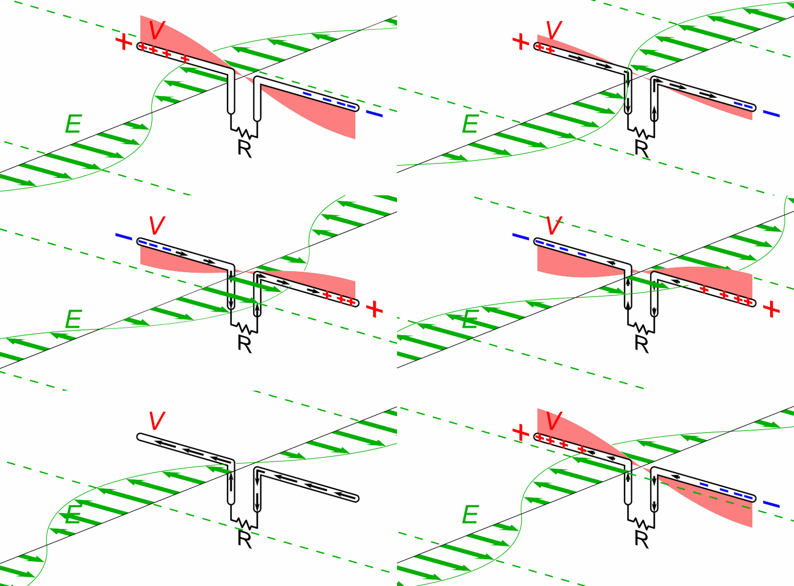
English: Animation showing a half-wave dipole antenna receiving power from a radio wave. The antenna consists of two metal rods each one-quarter of the wavelength long, attached through a parallel transmission line to a resistance R equal to the characteristic impedance of the antenna, representing the receiver. The electromagnetic wave is represented by its electric field (E, green arrows) (it should be kept in mind that the drawing only shows the field along one line, while the radio wave is actually a plane wave and the electric field is actually the same at every point on a plane perpendicular to the direction of motion). The wave's magnetic field is not shown. The oscillating electric field exerts force on the electrons in the antenna rods , causing them to move back and forth in currents (black arrows) between the ends of the antenna rods, charging the ends of the antenna alternately positive (+) and negative (−). Since the antenna is a half-wavelength long at the radio wave's frequency, it excites standing waves of voltage (V, red) and current in the antenna. The voltage along the antenna elements is represented graphically by a band of red whose thickness at any point is proportional to the magnitude of the voltage. The oscillating currents flowing back and forth from one antenna element to the other, pass down the transmission line and through the radio receiver, represented by R. In this animation the action is shown slowed down drastically; the radio waves received by dipoles actually oscillate back and forth at tens of thousands to billions of cycles per second. |
| Fecha | |
| Fuente | Trabajo propio |
| Autor | Chetvorno |
| Otras versiones |
Dipole receiving antenna animation 6 300ms.gif Slower version |

|
Esta circuit imagen volverse a crear usando gráficos vectoriales como un archivo SVG. Esto proporciona muchas ventajas, véase Commons:Media for cleanup (en inglés) para más información. Si ya hay una versión SVG de esta imagen disponible, por favor súbala a Commons. Tras subirla, reemplace esta plantilla con la plantilla
{{vector version available|nuevo nombre de imagen.svg}} en esta imagen.
Se recomienda nombrar el archivo SVG "Dipole receiving antenna animation 6 800x394x150ms.svg" - entonces la plantilla Vector version available (o Vva) no necesita el parámetro nuevo nombre de imagen. |
Licencia
[editar]| Este archivo está disponible bajo la licencia Creative Commons Dedicación de Dominio Público CC0 1.0 Universal. | |
| La persona que ha asociado una obra a este documento lo dedica al dominio público mediante la cesión mundial de sus derechos bajo la ley de derechos de autor y todos los derechos legales adyacentes propios de dicha, en el ámbito permitido por ley. Puedes copiar, modificar, distribuir y reproducir el trabajo, incluso con objetivos comerciales, sin pedir aprobación del autor.
http://creativecommons.org/publicdomain/zero/1.0/deed.enCC0Creative Commons Zero, Public Domain Dedicationfalsefalse |
Historial del archivo
Haz clic sobre una fecha y hora para ver el archivo tal como apareció en ese momento.
| Fecha y hora | Miniatura | Dimensiones | Usuario | Comentario | |
|---|---|---|---|---|---|
| actual | 07:47 7 jun 2015 |  | 800 × 394 (271 kB) | Chetvorno (discusión | contribs.) | User created page with UploadWizard |
No puedes sobrescribir este archivo.
Usos del archivo
Las siguientes páginas usan este archivo:
Uso global del archivo
Las wikis siguientes utilizan este archivo:
- Uso en ast.wikipedia.org
- Uso en bg.wikipedia.org
- Uso en bn.wikipedia.org
- Uso en ca.wikipedia.org
- Uso en da.wikipedia.org
- Uso en de.wikipedia.org
- Uso en en.wikipedia.org
- Uso en eo.wikipedia.org
- Uso en es.wikipedia.org
- Uso en eu.wikipedia.org
- Uso en fa.wikipedia.org
- Uso en fi.wikipedia.org
- Uso en fr.wikipedia.org
- Uso en fr.wiktionary.org
- Uso en hr.wikipedia.org
- Uso en it.wikipedia.org
- Uso en ja.wikipedia.org
- Uso en ku.wikipedia.org
- Uso en mk.wikipedia.org
- Uso en nl.wikipedia.org
- Uso en no.wikipedia.org
- Uso en pt.wikipedia.org
- Uso en ro.wikipedia.org
- Uso en ru.wikipedia.org
- Uso en sh.wikipedia.org
- Uso en sr.wikipedia.org
- Uso en th.wikipedia.org
- Uso en tl.wikipedia.org
Ver más uso global de este archivo.
Metadatos
Este archivo contiene información adicional, probablemente añadida por la cámara digital o el escáner usado para crearlo o digitalizarlo.
Si el archivo ha sido modificado desde su estado original, pueden haberse perdido algunos detalles.
| Comentario de archivo GIF | PhotoScape |
|---|
