File:PowerStation4.svg

Original file (SVG file, nominally 2,650 × 1,625 pixels, file size: 418 KB)
Captions
Captions
Summary[edit]
| Description |
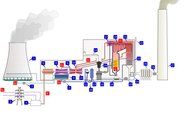
Tiếng Việt: Sơ đồ công nghệ của nhà máy nhiệt điện đốt than phun (PCC): (1) tháp làm mát, (2) bơm nước làm mát, (3) đường điện (3 pha), (4) biến thế (3 pha), (5) máy phát điện (3 pha), (6) tuabin hạ áp, (7) bơm nước ngưng, (8) bình ngưng, (9) tuabin trung áp, (10) van hơi, (11) tuabin cao áp, (12) bộ loại khí, (13) bình gia nhiệt, (14) băng chuyền than, (15) hứng than, (16) hệ phun bột than, (17) nồi hơi, (18) hệ thải xỉ, (19) giàn quá nhiệt, (20) quạt gió, (21) hối nhiệt, (22) đường cấp khí, (23) bộ trao đổi nhiệt, (24) gia nhiệt cấp khí, (25) bộ khử bụi, (26) quạt khói, (27) ống khói, (28) bơm nước cấp; (Q) nhiệt lượng tỏa ra từ nhiên liệu, tiêu thụ bởi nhà máy, (D) phụ tải hơi của lò hơi, (D0) tiêu hao nhiệt hơi cho tuabin, (DL) tổn thất nhiệt hơi trên đường ống, (DK) nhiệt lượng của hơi đưa vào bình ngưng, (E) điện năng sản xuất được, (E0) điện năng cung cấp cho các hộ tiêu dùng (thấp hơn E, một phần do trích lại cho nhà máy điện tự dùng, để vận hành các bơm và các hệ thống khác), (QK) tổn thất nhiệt làm mát bình ngưng.
English: A coal-fired thermal power station. Modified from File:PowerStation2.svg, adding heat & electricity energy flow notes in red boxes.
1. Cooling tower. 2. Cooling water pump. 3. Transmission line (3-phase). 4. Unit transformer (3-phase). 5. Electric generator (3-phase). 6. Low pressure turbine. 7. Condensate extraction pump. 8. Condensor. 9. Intermediate pressure turbine. 10. Steam governor valve. 11. High pressure turbine. 12. Deaerator. 13. Feed heater. 14. Coal conveyor. 15. Coal hopper. 16. Pulverised fuel mill. 17. Boiler drum. 18. Ash hopper. 19. Superheater. 20. Forced draught fan. 21. Reheater. 22. Air intake. 23. Economiser. 24. Air preheater. 25. Precipitator. 26. Induced draught fan. 27. Chimney stack. 28. Feed pump. Coal is conveyed (14) from an external stack and ground to a very fine powder by large metal spheres in the pulverised fuel mill (16). There it is mixed with preheated air (24) driven by the forced draught fan (20). The hot air-fuel mixture is forced at high pressure into the boiler where it rapidly ignites. Water of a high purity flows vertically up the tube-lined walls of the boiler, where it turns into steam, and is passed to the boiler drum, where steam is separated from any remaining water. The steam passes through a manifold in the roof of the drum into the pendant superheater (19) where its temperature and pressure increase rapidly to around 200 bar and 570°C, sufficient to make the tube walls glow a dull red. The steam is piped to the high pressure turbine (11), the first of a three-stage turbine process. A steam governor valve (10) allows for both manual control of the turbine and automatic set-point following. The steam is exhausted from the high pressure turbine, and reduced in both pressure and temperature, is returned to the boiler reheater (21). The reheated steam is then passed to the intermediate pressure turbine (9), and from there passed directly to the low pressure turbine set (6). The exiting steam, now a little above its boiling point, is brought into thermal contact with cold water (pumped in from the cooling tower) in the condensor (8), where it condenses rapidly back into water, creating near vacuum-like conditions inside the condensor chest. The condensed water is then passed by a condensate pump (7) to a deaerator (12), then pumped by feedwater pump (28) and pre-warmed, first in a feed heater (13) powered by steam drawn from the high pressure set, and then in the economiser (23), before being returned to the boiler drum. The cooling water from the condensor is sprayed inside a cooling tower (1), creating a highly visible plume of water vapor, before being pumped back to the condensor (8) in cooling water cycle. The three turbine sets are sometimes coupled on the same shaft as the three-phase electrical generator (5) which generates an intermediate level voltage (typically 20-25 kV). This is stepped up by the unit transformer (4) to a voltage more suitable for transmission (typically 250-500 kV) and is sent out onto the three-phase transmission system (3). Exhaust gas from the boiler is drawn by the induced draft fan (26) through an electrostatic precipitator (25) and is then vented through the chimney stack (27).Русский: Схема ГРЭС на угле: 1 — градирня; 2 — циркуляционный насос; 3 — линия электропередачи; 4 — повышающий трансформатор; 5 — турбогенератор; 6 — цилиндр низкого давления паровой турбины; 7 — конденсатный насос; 8 — поверхностный конденсатор; 9 — цилиндр среднего давления паровой турбины; 10 — стопорный клапан; 11 — цилиндр высокого давления паровой турбины; 12 — деаэратор; 13 — регенеративный подогреватель; 14 — транспортёр топливоподачи; 15 — бункер угля; 16 — мельница угля; 17 — барабан котла; 18 — система шлакоудаления; 19 — пароперегреватель; 20 — дутьевой вентилятор; 21 — промежуточный пароперегреватель; 22 — воздухозаборник; 23 — экономайзер; 24 — регенеративный воздухоподогреватель; 25 — фильтр; 26 — дымосос; 27 — дымовая труба; 28 — питательный насос. |
| Date | |
| Source | Own work |
| Author | Tttrung |
| Other versions |
|
| SVG development | This diagram was created with Inkscape. This diagram uses embedded text that can be easily translated using a text editor. |


Licensing[edit]
- You are free:
- to share – to copy, distribute and transmit the work
- to remix – to adapt the work
- Under the following conditions:
- attribution – You must give appropriate credit, provide a link to the license, and indicate if changes were made. You may do so in any reasonable manner, but not in any way that suggests the licensor endorses you or your use.
- share alike – If you remix, transform, or build upon the material, you must distribute your contributions under the same or compatible license as the original.
File history
Click on a date/time to view the file as it appeared at that time.
| Date/Time | Thumbnail | Dimensions | User | Comment | |
|---|---|---|---|---|---|
| current | 04:17, 8 May 2021 | | 2,650 × 1,625 (418 KB) | Tttrung (talk | contribs) | minor improve in size |
| 04:16, 8 May 2021 |  | 2,688 × 1,625 (418 KB) | Tttrung (talk | contribs) | update size again | |
| 04:15, 8 May 2021 |  | 2,625 × 1,688 (418 KB) | Tttrung (talk | contribs) | update size of image | |
| 04:11, 8 May 2021 |  | 2,500 × 1,563 (418 KB) | Tttrung (talk | contribs) | Uploaded own work with UploadWizard |
You cannot overwrite this file.
File usage on Commons
The following 2 pages use this file: