File:Inductively coupled crystal radio circuit.svg
Siirry navigaatioon
Siirry hakuun

Tämän PNG-esikatselun koko koskien SVG-tiedostoa: 722 × 435 kuvapistettä. Muut resoluutiot: 320 × 193 kuvapistettä | 640 × 386 kuvapistettä | 1 024 × 617 kuvapistettä | 1 280 × 771 kuvapistettä | 2 560 × 1 542 kuvapistettä.
Alkuperäinen tiedosto (SVG-tiedosto; oletustarkkuus 722 × 435 kuvapistettä; tiedostokoko 36 KiB)
Kuvatekstit
Kuvatekstit
Lisää yhden rivin pituinen kuvaus tästä tiedostosta
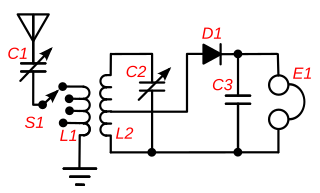
Circuit of a crystal radio
Yhteenveto[muokkaa]
| Kuvaus |
English: A circuit of an inductively-coupled crystal radio receiver with impedance matching. This type of circuit, called a "two circuit" or "loose coupler" receiver, was used in most sophisticated crystal receivers from the wireless telegraphy era which ended in the 1920s, until today. Instead of a single tuning coil, it has an antenna coupling transformer (L1,L2) which improves the poor selectivity found in most crystal receivers. Each coil functions as a tuned circuit; the primary L1 resonating with the capacitance of the antenna and the primary tuning capacitor C1 and the secondary resonating with the secondary tuning capacitor C2. The two tuned circuits interact, resulting in a much narrower bandwidth (higher Q) than a single tuned circuit when the two coils are loosely coupled. However looser coupling also reduces the amount of signal getting through the transformer. So the coupling was made adjustable. When interference was encountered the coils were separated to sharpen the bandwidth and reject the interference. Adjustable antenna matching is provided by attaching the antenna to a tap on L1 which can be selected by switch S1. This maximizes the power transferred from the antenna to the receiver by matching the low impedance of the antenna-ground circuit (around 10-200 ohms) to the higher impedance of the tuned circuits, using L1 - L2 as an impedance matching transformer. The turns ratio was adjusted with switch S1 until the station sounded loudest in the earphone E1. To improve power transfer the crystal detector D1 is also impedance matched to the tuned circuit by attaching it to a tap on L2. This also improves the Q of the tuned circuit, increasing the selectivity, because it reduces the resistive "loading" of the diode-earphone circuit on the tuned circuit. |
| Päiväys | |
| Lähde | Oma teos |
| Tekijä | Chetvorno |
| SVG kehittely | Tämä vektorigrafiikkatiedosto luotiin käyttäen apuna ohjelmaa Inkscape, or with something else. This diagram uses translateable embedded text. |
Lisenssi[muokkaa]
I, Chetvorno, the author of this work, release it into the public domain for any use whatever.
| Minä, tämän teoksen tekijänoikeudellinen omistaja, julkaisen tämän teoksen public domainiin eli luovun kaikista tekijänoikeuksista lain sallimissa puitteissa. Tämä on voimassa maailmanlaajuisesti. Joissain maissa laki ei mahdollista tätä. Mikäli näin on: Myönnän kenelle tahansa oikeuden käyttää tätä teosta mihin tahansa tarkoitukseen, ilman mitään ehtoja, ellei laki vaadi ehtojen asettamista. |
Tiedoston historia
Päiväystä napsauttamalla näet, millainen tiedosto oli kyseisellä hetkellä.
| Päiväys | Pienoiskuva | Koko | Käyttäjä | Kommentti | |
|---|---|---|---|---|---|
| nykyinen | 9. toukokuuta 2017 kello 04.15 | | 722 × 435 (36 KiB) | Chetvorno (keskustelu | muokkaukset) | Replaced invalid version with "plain SVG" version that passes validation |
| 28. tammikuuta 2016 kello 02.16 |  | 722 × 435 (47 KiB) | Chetvorno (keskustelu | muokkaukset) | Increased line width and tweaked location of components | |
| 20. toukokuuta 2010 kello 10.35 |  | 748 × 426 (48 KiB) | Chetvorno (keskustelu | muokkaukset) | {{Information |Description={{en|A circuit of an inductively coupled Wikipedia:crystal radio receiver with Wikipedia:impedance matching. This type of circuit, called a "two circuit" or "loose coupler" receiver, was used in the most sophisticated |
Et voi tallentaa uutta tiedostoa tämän tilalle.
Tiedoston käyttö
Tätä tiedostoa ei käytetä millään sivulla.
Tiedoston järjestelmänlaajuinen käyttö
Seuraavat muut wikit käyttävät tätä tiedostoa:
- Käyttö kohteessa da.wikipedia.org
- Käyttö kohteessa en.wikipedia.org
- Käyttö kohteessa es.wikipedia.org
- Käyttö kohteessa fi.wikipedia.org
- Käyttö kohteessa fr.wikipedia.org