File:Two slider crystal radio circuit.svg
Ir a la navegación
Ir a la búsqueda

Tamaño de esta previsualización PNG del archivo SVG: 382 × 417 píxeles. Otras resoluciones: 220 × 240 píxeles | 440 × 480 píxeles | 703 × 768 píxeles | 938 × 1024 píxeles | 1876 × 2048 píxeles.
Archivo original (archivo SVG, nominalmente 382 × 417 píxeles, tamaño de archivo: 18 kB)
Leyendas
Leyendas
Añade una explicación corta acerca de lo que representa este archivo
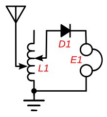
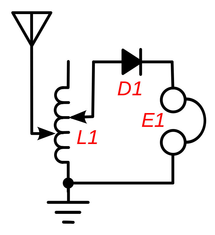
Circuit of a crystal radio
Resumen
[editar]
| Descripción |
English: Circuit of a "two-slider" crystal radio receiver, a popular circuit used in simple crystal radios made before 1920. To tune in different stations, it used a tuning coil (L1) with two sliding contacts on it. It doesn't use a tuning capacitor, instead the coil resonates with the capacitance of the long wire antenna to create a tuned circuit. The left-hand slider tunes the receiver to different stations, allowing more or less of the coil's turns in parallel with the antenna capacitance. The right-hand slider adjusts the impedance match between the antenna and the rest of the circuit, to maximise the power transferred from the antenna into the receiver. It is adjusted until the station sounds loudest in the earphone (E1). The coil acts as an impedance matching transformer to match the low impedance (10-200 ohms) of the antenna-ground circuit with the higher impedance (thousands of ohms) of the coil at resonance. The two adjustments were interactive, so adjusting the right slider also detuned the radio, requiring retuning. |
| Fecha | |
| Fuente | Trabajo propio |
| Autor | Chetvorno |
| SVG desarrollo | El código fuente de esta imagen SVG es válido. This diagram uses translateable embedded text. |
Licencia
[editar]
I, Chetvorno, the author of this work, release it into the public domain for any use whatever
| Yo, el titular de los derechos de autor de esta obra, lo libero al dominio público. Esto aplica en todo el mundo. En algunos países esto puede no ser legalmente factible; si ello ocurriese: Concedo a cualquier persona el derecho de usar este trabajo para cualquier propósito, sin ningún tipo de condición al menos que éstas sean requeridas por la ley. |
Historial del archivo
Haz clic sobre una fecha y hora para ver el archivo tal como apareció en ese momento.
| Fecha y hora | Miniatura | Dimensiones | Usuario | Comentario | |
|---|---|---|---|---|---|
| actual | 04:09 9 may 2017 | | 382 × 417 (18 kB) | Chetvorno (discusión | contribs.) | Replaced with "plain SVG" version which passes validation |
| 02:22 28 ene 2016 |  | 382 × 417 (24 kB) | Chetvorno (discusión | contribs.) | Increased line width and tweaked location of components | |
| 07:34 20 may 2010 |  | 384 × 424 (24 kB) | Chetvorno (discusión | contribs.) | {{Information |Description={{en|Circuit of a "two-slider" Wikipedia:crystal radio receiver, a common circuit used in simple crystal radios made before 1920. To tune in different stations, it used a tuning coil ''L1'' with two sliding contacts on it. |
No puedes sobrescribir este archivo.
Usos del archivo
No hay páginas que enlacen a este archivo.
Uso global del archivo
Las wikis siguientes utilizan este archivo:
- Uso en en.wikipedia.org
- Uso en es.wikipedia.org