File:Jet engine numbered.svg
Jump to navigation
Jump to search

Size of this PNG preview of this SVG file: 800 × 334 pixels. Other resolutions: 320 × 134 pixels | 640 × 267 pixels | 1,024 × 428 pixels | 1,280 × 535 pixels | 2,560 × 1,069 pixels | 910 × 380 pixels.
Original file (SVG file, nominally 910 × 380 pixels, file size: 447 KB)
Captions
Captions
Add a one-line explanation of what this file represents
Summary[edit]
| Description |
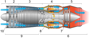
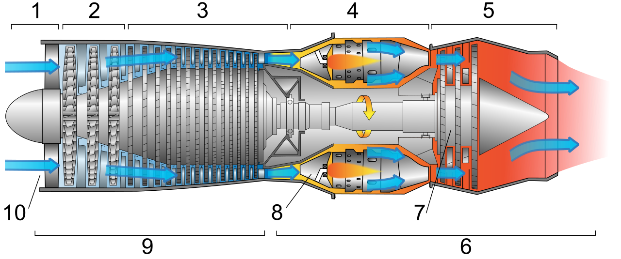
Deutsch: Schemazeichnung eines typischen Gasturbinen-Triebwerks. Luft wird durch die Gebläsesschaufeln im Verdichterabschnitt komprimiert, wenn sie in die Turbine eintritt. Sie wird mit Kraftstoff gemischt und im Verbrennungsabschnitt verbrannt. Die heißen Abgase entwickeln Schub nach vorne und drehen die Turbinenschaufeln und damit die Gebläseschaufeln im Verdichterabschnitt.
English: Diagram of a typical gas turbine jet engine. Air is compressed by the fan blades as it enters the engine, and it is mixed and burned with fuel in the combustion section. The hot exhaust gases provide forward thrust and turn the turbines which drive the compressor fan blades.
Français : Schéma montrant un turboréacteur d'avion typique (simple flux, simple corps). L'air est comprimé par les pales en entrant dans le réacteur, puis est mélangé avec le carburant qui brule dans la chambre de combustion. Les gaz d'échappement génèrent une forte réaction vers l'avant, et font également tourner les turbines qui actionnent les pales de compression.
Español: Esquema de un motor estándar a reacción. El aire es comprimido por las palas del ventilador, para ser mezclado con el carburante y explosionado en la cámara de compresión. La salida de los gases realiza un fuerte empuje hacia delante y hacen girar las turbinas que accionan las palas de compresión.
Català: Esquema d'un motor estàndard a reacció. L'aire d'entrada es comprimit per les pales o àleps del ventilador, per ser seguidament barrejat amb el combustible a la cambra de combustió. La sortida dels gasos provoca l'impuls i fa girar les turbines, les quals mouen les pales de compressió.
Română: Schema unei turbine cu gaze. Aerul introdus este comprimat de paletele compresorului, după care intră în camera de ardere, unde este introdus combustibil. Amestecul este aprins, iar gazele de ardere se destind în turbină, efectuând lucru mecanic. În imagine sunt specificate următoarele părţi componente:
Русский: Схема турбореактивного двигателя. Воздух сжимается лопастями компрессора, смешивается с топливом, смесь поступает в камеру сгорания. Горячие выхлопные газы обеспечивают движение вперёд и приводят в действие компрессор.
Polski: Schemat jednoprzepływowego silnika turboodrzutowego. Powietrze pod ciśnieniem wtłaczane jest przez sprężarkę do komory spalania gdzie dostarczane jest paliwo i zachodzi proces spalania. Gorące spaliny napędzają turbinę połączona wałem ze sprężarką.
Tiếng Việt: Sơ đồ của một động cơ turbin phản lực. Không khí được nén từ các quạt khi nó đi vào động cơ, và nó được trộn và bị đốt với nhiên nhiệu trong buồng đốt.
中文:一个典型的燃气涡轮喷气发动机图解。上面流程标识为:
|
||
| Date | (UTC) | ||
| Source | Own work, vector version of en:Image:FAA-8083-3A Fig 14-1.PNG which comes from an FAA handbook | ||
| Author | Jeff Dahl | ||
| Other versions |
[]
|
||
| SVG development | This vector image was created with Inkscape, or with something else. |

.PNG)

|

This image was selected as picture of the day on Wikimedia Commons for 2 April 2008. It was captioned as follows: English: Diagram of a typical gas turbine jet engine. Other languages:
Afrikaans: Diagram van 'n tipiese gasturbine stralerenjin Alemannisch: Äs Diagram vom a nä Strautriebwärch Asturianu: Cadarma d'un reautor. Bosanski: Dijagram tipičnog avionskog benzinskog motora. Čeština: Schematické znázornění proudového motoru Deutsch: Diagramm eines Strahltriebwerks English: Diagram of a typical gas turbine jet engine. Español: Diagrama de un reactor. Euskara: Erreakzio-motore baten diagrama. Français : Schéma montrant un turboréacteur d'avion typique Íslenska: Skýringarmynd sem sýnir dæmigerðan þotuhreyfil. Italiano: Schema di un motore a getto. Lietuvių: Tipiška dujų turbinos reaktyvinio variklio diagrama. Magyar: Gázturbinás sugárhajtómű felépítése Nederlands: diagram van een tunnelschroefturbine Português: Diagrama esquemático de uma típica turbina a gás. Română: Schemă numerotată a celei mai comune turbinei cu gaze folosită în aviație. Svenska: Schematisk bild av en turbinjetmotor. Беларуская: Схема газавай турбіны рэактыўнага рухавіка Русский: Схема турбореактивного двигателя. Српски / srpski: Дијаграм типичне авионске бензинске турбине (мотора). 한국어: 전형적인 가스 터빈 제트 엔진의 다이어그램. 中文: 一个典型的燃气涡轮喷气发动机图解 |
This image was selected as picture of the day on Vietnamese Wikipedia.
|
Licensing[edit]
Jeff Dahl, the copyright holder of this work, hereby publishes it under the following licenses:

|
Permission is granted to copy, distribute and/or modify this document under the terms of the GNU Free Documentation License, Version 1.2 or any later version published by the Free Software Foundation; with no Invariant Sections, no Front-Cover Texts, and no Back-Cover Texts. A copy of the license is included in the section entitled GNU Free Documentation License. |
This file is licensed under the Creative Commons Attribution-Share Alike 4.0 International, 3.0 Unported, 2.5 Generic, 2.0 Generic and 1.0 Generic license.
Attribution: Jeff Dahl
- You are free:
- to share – to copy, distribute and transmit the work
- to remix – to adapt the work
- Under the following conditions:
- attribution – You must give appropriate credit, provide a link to the license, and indicate if changes were made. You may do so in any reasonable manner, but not in any way that suggests the licensor endorses you or your use.
- share alike – If you remix, transform, or build upon the material, you must distribute your contributions under the same or compatible license as the original.
You may select the license of your choice.
| Annotations | This image is annotated: View the annotations at Commons |
File history
Click on a date/time to view the file as it appeared at that time.
| Date/Time | Thumbnail | Dimensions | User | Comment | |
|---|---|---|---|---|---|
| current | 04:25, 8 January 2008 | | 910 × 380 (447 KB) | Jeff Dahl (talk | contribs) | Label fixes |
| 18:45, 7 January 2008 |  | 910 × 380 (444 KB) | Jeff Dahl (talk | contribs) | stroke to path | |
| 18:43, 7 January 2008 |  | 910 × 380 (444 KB) | Jeff Dahl (talk | contribs) | Bracket fixes | |
| 18:40, 7 January 2008 |  | 910 × 380 (443 KB) | Jeff Dahl (talk | contribs) | Bracket fixes | |
| 18:37, 7 January 2008 |  | 910 × 380 (443 KB) | Jeff Dahl (talk | contribs) | bracket fixes | |
| 18:32, 7 January 2008 |  | 910 × 380 (443 KB) | Jeff Dahl (talk | contribs) | rm whitespace | |
| 07:09, 7 January 2008 | 1,000 × 400 (444 KB) | Jeff Dahl (talk | contribs) | {{Inkscape}} {{Information |Description={{en|Diagram of a typical gas turbine jet engine.}} |Source=self-made |Date=~~~~~ |Author= Jeff Dahl |Permission= |other_versions=100px }} |
You cannot overwrite this file.
File usage on Commons
The following 82 pages use this file:
- Schemes
- Wikimedia Conference Japan 2009/Commons写真展
- User:Miya/Introduction
- User:Miya/POTY/Diagrams2008
- User:Notafish/Votes 2008
- User:Rocket000/SVGs/Transportation
- User:Werneuchen
- User talk:Jeff Dahl
- Commons:Featured picture candidates/Image:Jet engine numbered.svg
- Commons:Featured picture candidates/Log/January 2008
- Commons:Featured pictures/Non-photographic media/Computer-generated
- Commons:Featured pictures/chronological/2008-A
- Commons:Picture of the Year/2008/Galleries/All
- Commons:Picture of the Year/2008/Galleries/Diagrams
- Commons:Picture of the Year/2008/Results/Round 1/Gallery/All
- Commons:Picture of the Year/2008/Results/Round 1/Gallery/Diagrams
- Commons:Picture of the Year 2008/File:Jet engine numbered.svg
- Commons:Potd/2008-04 (de)
- Commons:Potd/2008-04 (eo)
- Commons:Potd/2008-04 (nl)
- Commons:Potd/2008-04 (pl)
- Commons:Potd/2008-04 (pt)
- Commons:Potd/2008-04 (ro)
- Commons:Potd/2008-04 (tr)
- Commons:Potd/2008-04 (zh-hant)
- File:550px-Jet engine svg arabic.png
- File:Jet engine-Pashto.svg
- File:Jet engine-Persian.svg
- File:Jet engine-bn.svg
- File:Jet engine-gu.svg
- File:Jet engine-kn.svg
- File:Jet engine-mr.svg
- File:Jet engine-ru.svg
- File:Jet engine-tamil.svg
- File:Jet engine-te.svg
- File:Jet engine.svg
- File:Jet engine (Bangla).svg
- File:Jet engine French.svg
- File:Jet engine HEB.svg
- File:Jet engine arabic.svg
- File:Jet engine as.svg
- File:Jet engine de.svg
- File:Jet engine ml.svg
- File:Jet engine numbered.svg
- File:Jet engine spanish.svg
- File:Jet engine sv.svg
- File:Jet engine turkish.svg
- File:जेट इंजन.svg
- File:ジェット・エンジンの動作原理(詳細図).PNG
- Template:Other versions/Jet engine
- Template:Potd/2008-04
- Template:Potd/2008-04-02
- Template:Potd/2008-04-02 (af)
- Template:Potd/2008-04-02 (als)
- Template:Potd/2008-04-02 (ast)
- Template:Potd/2008-04-02 (be)
- Template:Potd/2008-04-02 (bs)
- Template:Potd/2008-04-02 (cs)
- Template:Potd/2008-04-02 (da)
- Template:Potd/2008-04-02 (de)
- Template:Potd/2008-04-02 (en)
- Template:Potd/2008-04-02 (es)
- Template:Potd/2008-04-02 (eu)
- Template:Potd/2008-04-02 (fr)
- Template:Potd/2008-04-02 (hu)
- Template:Potd/2008-04-02 (is)
- Template:Potd/2008-04-02 (it)
- Template:Potd/2008-04-02 (ja)
- Template:Potd/2008-04-02 (ko)
- Template:Potd/2008-04-02 (lt)
- Template:Potd/2008-04-02 (nl)
- Template:Potd/2008-04-02 (pam)
- Template:Potd/2008-04-02 (pl)
- Template:Potd/2008-04-02 (pt)
- Template:Potd/2008-04-02 (ro)
- Template:Potd/2008-04-02 (ru)
- Template:Potd/2008-04-02 (sr)
- Template:Potd/2008-04-02 (sv)
- Template:Potd/2008-04-02 (tr)
- Template:Potd/2008-04-02 (zh-hans)
- Template:Potd/2008-04-02 (zh-hant)
- Template:Potd/2008-04 (zh-hans)
.svg)
File usage on other wikis
The following other wikis use this file:
- Usage on ar.wikipedia.org
- Usage on az.wikipedia.org
- Usage on ba.wikipedia.org
- Usage on be.wikipedia.org
- Usage on bn.wikipedia.org
- Usage on ca.wikipedia.org
- Usage on crh.wikipedia.org
- Usage on cv.wikipedia.org
- Usage on de.wikipedia.org
- Usage on en.wikipedia.org
- Usage on es.wikipedia.org
- Usage on eu.wikipedia.org
- Usage on hu.wikipedia.org
- Usage on hy.wikipedia.org
- Usage on it.wikipedia.org
- Usage on ko.wikipedia.org
- Usage on lbe.wikipedia.org
- Usage on mg.wikipedia.org
- Usage on nl.wikipedia.org
- Usage on nl.wiktionary.org
- Usage on os.wikipedia.org
- Usage on outreach.wikimedia.org
- Usage on pl.wikipedia.org
- Usage on pt.wikipedia.org
- Usage on ru.wikipedia.org
- Usage on ru.wikinews.org
View more global usage of this file.