Category:Hand-drawn electronic circuit diagrams
Jump to navigation
Jump to search
| Upload media | |||||
| |||||
Subcategories
This category has the following 2 subcategories, out of 2 total.
C
V
Media in category "Hand-drawn electronic circuit diagrams"
The following 159 files are in this category, out of 159 total.
-
741 input stab block 1000.jpg 1,000 × 614; 91 KB
-
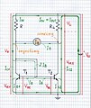
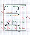
741 input stab detail 1000.jpg 1,000 × 1,277; 200 KB
-
741 input stab tca 1000.jpg 1,000 × 685; 105 KB
-
Active rc integrator how to convert 450.jpg 450 × 650; 33 KB
-
Antilog volt comp 1000.jpg 1,000 × 712; 114 KB
-
Antilog volt comp graph 1000.jpg 1,000 × 714; 103 KB
-
Bistable inic 1a 1000.jpg 1,000 × 746; 110 KB
-
Bistable inic 1b 1000.jpg 1,000 × 744; 108 KB
-
Bootstrapped current source 65b 1000.jpg 1,000 × 731; 58 KB
-
Cap dif volt comp 1000.jpg 1,000 × 713; 112 KB
-
Chung 1 1000.jpg 1,000 × 1,428; 190 KB
-
Chung 2 1000.jpg 1,000 × 1,425; 195 KB
-
Chung 3 1000.jpg 1,000 × 1,425; 198 KB
-
Chung 4 1000.jpg 1,000 × 759; 142 KB
-
Chung 5 1000.jpg 1,000 × 757; 134 KB
-
Commonemiterbasic.jpg 1,101 × 1,192; 782 KB
-
Compensatingopamp.jpg 1,898 × 918; 848 KB
-
Creating nic 1000.jpg 1,000 × 707; 73 KB
-
Creating simplest neg rez 1000.jpg 1,000 × 709; 106 KB
-
Creating simplest neg rez.jpg 2,504 × 1,832; 730 KB
-
Creating simplest op-amp neg rez 1000.jpg 1,000 × 711; 110 KB
-
Current mirror sinking and sucking2ib 1 a 1000.jpg 1,000 × 1,201; 177 KB
-
Current mirror sinking and sucking2ib a 1000.jpg 1,000 × 1,187; 161 KB
-
Current mirror sucking2ib a 1000.jpg 1,000 × 1,195; 164 KB
-
Current mirror trans diode whiteboard 66b.jpg 480 × 640; 26 KB
-
Current-driven neg resistor idea 1000.jpg 1,000 × 712; 96 KB
-
Current-to-voltage1.jpg 1,600 × 1,200; 267 KB
-
Dans knife switch circuit.jpg 1,600 × 1,200; 514 KB
-
Diagramlab1.jpg 1,906 × 1,069; 249 KB
-
ECL structure 1000.jpg 1,000 × 714; 106 KB
-
Emitterfollowe1.jpg 2,272 × 1,704; 1.86 MB
-
Equilibrium 1000.jpg 1,000 × 599; 41 KB
-
Ex1sch1.jpg 1,751 × 913; 1.02 MB
-
Ex1sch2.jpg 1,883 × 957; 191 KB
-
Ex1sch3.jpg 1,945 × 963; 512 KB
-
Ex1sch4.jpg 1,933 × 963; 1.19 MB
-
Feedbackprinciple.jpg 876 × 753; 446 KB
-
Finalgyrator.jpg 1,719 × 858; 591 KB
-
Finatljbtcircuit.jpg 2,053 × 1,097; 1.36 MB
-
Flying follower volt comp 1000.jpg 1,000 × 711; 113 KB
-
Follower volt comp 1000.jpg 1,000 × 710; 113 KB
-
Followercomplete.jpg 2,024 × 1,434; 1.46 MB
-
Functional bridge INIC.JPG 1,976 × 2,008; 147 KB
-
Functional bridge VNIC.JPG 2,010 × 2,020; 142 KB
-
Gyratorinitial.jpg 1,874 × 918; 605 KB
-
Hodiny.gif 775 × 502; 18 KB
-
How to introduce ser nfb 450.jpg 450 × 617; 35 KB
-
Howland current source 1000.jpg 1,000 × 724; 82 KB
-
I-inverted resistor - fixed gain amp implementation.JPG 3,064 × 2,016; 306 KB
-
I-inverted resistor - source implementation.JPG 3,080 × 2,004; 247 KB
-
I-inverted resistor.JPG 2,708 × 1,532; 167 KB
-
I-to-v in res 1000.jpg 1,000 × 696; 46 KB
-
I-to-v out res 1000.jpg 1,000 × 695; 47 KB
-
Ideal current source 65b.jpg 1,744 × 2,448; 153 KB
-
Ind int volt comp 1000.jpg 1,000 × 711; 110 KB
-
Inv ampl volt comp 1000.jpg 1,000 × 711; 116 KB
-
Invertingaplifier.jpg 1,814 × 925; 882 KB
-
Iv curves4 N 1000.jpg 1,000 × 751; 67 KB
-
Lab299.jpg 1,280 × 960; 97 KB
-
Lab2rs.jpg 1,280 × 960; 209 KB
-
Lab2rs2.jpg 1,280 × 960; 204 KB
-
Lab2rs3.jpg 1,280 × 960; 190 KB
-
Lab2rs4.jpg 1,280 × 960; 191 KB
-
Lab303.jpg 1,204 × 631; 45 KB
-
Linear inic 0b 1000.jpg 1,000 × 1,393; 203 KB
-
Linear inic 10b 1000.jpg 1,000 × 719; 115 KB
-
Linear inic 1b 1000.jpg 1,000 × 667; 95 KB
-
Linear inic 2b 1000.jpg 1,000 × 730; 120 KB
-
Linear inic 3b 1000.jpg 1,000 × 729; 110 KB
-
Linear inic 4b 1000.jpg 1,000 × 735; 113 KB
-
Linear inic 5b 1000.jpg 1,000 × 728; 116 KB
-
Linear inic 6b 1000.jpg 1,000 × 730; 110 KB
-
Linear inic 6b temp.jpg 3,056 × 2,232; 977 KB
-
Linear inic 7b 1000.jpg 1,000 × 749; 119 KB
-
Linear inic 8b 1000.jpg 1,000 × 731; 114 KB
-
Linear inic 9b 1000.jpg 1,000 × 715; 115 KB
-
Loaded volt divider 1000.jpg 1,000 × 707; 49 KB
-
Localisation template.JPG 2,048 × 1,536; 630 KB
-
Microlab setup 1000.jpg 1,000 × 687; 75 KB
-
Neg imp current comp 1000.jpg 1,000 × 714; 105 KB
-
Neg imp volt compensation 1 1000.jpg 1,000 × 707; 104 KB
-
Neg imp volt compensation 1000.jpg 1,000 × 710; 103 KB
-
Neg imp volt compensation 2 1000.jpg 1,000 × 704; 103 KB
-
Neg imp volt compensation 3 1000.jpg 1,000 × 708; 103 KB
-
Neg imp volt compensation 4 1000.jpg 1,000 × 707; 104 KB
-
Nfb block-diagram 65b 1000.jpg 1,000 × 809; 35 KB
-
NIC can act either as VNIC or INIC.JPG 2,553 × 1,464; 159 KB
-
Op amp integrator volt comp 1000.jpg 1,000 × 708; 106 KB
-
Op-amp INIC.JPG 3,048 × 2,048; 312 KB
-
Op-amp VNIC.JPG 2,996 × 2,000; 272 KB
-
Opampbasic.jpg 2,268 × 1,277; 1.43 MB
-
Opamplifier.jpg 1,238 × 901; 909 KB
-
Par summer active 1000.jpg 1,000 × 689; 57 KB
-
Par summer block 1000.jpg 1,000 × 709; 29 KB
-
Par summer block 450.jpg 450 × 229; 9 KB
-
Par summer current 1000.jpg 1,000 × 708; 48 KB
-
Par summer dac 1000.jpg 1,000 × 677; 35 KB
-
Par summer visualized 1000.jpg 1,000 × 676; 60 KB
-
Parallel-connected resistor idea 1000.jpg 1,000 × 709; 98 KB
-
Passive current source 65b 1000.jpg 1,000 × 708; 53 KB
-
Passive i-to-v converter 1000.jpg 1,000 × 688; 58 KB
-
Positivefedbackquestion.jpg 918 × 679; 436 KB
-
RC integrator 1000.jpg 1,000 × 710; 55 KB
-
RC integrator 10002.jpg 1,000 × 710; 143 KB
-
Real grounds 1000.jpg 1,000 × 707; 54 KB
-
Reset.jpg 1,152 × 582; 31 KB
-
Ser neg resistor idea 1000.jpg 1,000 × 706; 59 KB
-
Ser summer block 450.jpg 450 × 256; 7 KB
-
Ser summer emitter follower 1000.jpg 1,000 × 685; 53 KB
-
Ser summer flying load 1000.jpg 906 × 543; 41 KB
-
Ser summer flying sources 1000.jpg 900 × 541; 41 KB
-
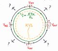
Ser summer loop 1000.jpg 1,000 × 868; 49 KB
-
Series-connected resistor idea 1000.jpg 1,000 × 708; 95 KB
-
Shéma du corps.JPG 1,536 × 2,048; 582 KB
-
Simple current mirror a 1000.jpg 1,000 × 1,199; 168 KB
-
Simplest current source 65b 1000.jpg 1,000 × 712; 37 KB
-
Simulated inductor idea 1000.jpg 1,000 × 685; 47 KB
-
Simulted inductor basic idea 1000.jpg 1,000 × 816; 114 KB
-
Steady sources 1000.jpg 1,000 × 710; 36 KB
-
Stray capacitance neutralized idea 1000.jpg 1,000 × 777; 124 KB
-
Stray capacitance neutralized impl 1000.jpg 1,000 × 790; 136 KB
-
Trans ampl 1000.jpg 1,000 × 538; 66 KB
-
Trans ser nfb 450.jpg 450 × 643; 36 KB
-
Trans ser nfb idea 450.jpg 450 × 639; 36 KB
-
Transimpedance ampl as nic 1000.jpg 1,000 × 706; 79 KB
-
V-inverted resistor - fixed gain amp implementation.JPG 3,068 × 2,008; 288 KB
-
V-inverted resistor - source implementation.JPG 3,104 × 2,016; 274 KB
-
V-inverted resistor.JPG 2,772 × 1,596; 182 KB
-
V-to-i converter rc integrator 1000.jpg 1,000 × 679; 65 KB
-
Volt comp old idea 1992 1000.jpg 1,000 × 703; 123 KB
-
Volt divider 1000.jpg 1,000 × 707; 47 KB
-
Volt driven neg imp element 100.jpg 100 × 70; 2 KB
-
Volt driven neg imp element 1000.jpg 1,000 × 707; 85 KB
-
Volt driven neg resistor ampl 1000.jpg 1,000 × 707; 99 KB
-
Volt driven resistor ampl 1000.jpg 1,000 × 707; 78 KB
-
Volt driven resistor op-amp 1000.jpg 1,000 × 707; 105 KB
-
Voltage compensation 1 1000.jpg 1,000 × 709; 97 KB
-
Voltage compensation 2 1000.jpg 1,000 × 713; 101 KB
-
Voltage compensation 2a 1000.jpg 1,000 × 712; 107 KB
-
Voltage compensation 3 1000.jpg 1,000 × 715; 100 KB
-
Voltage compensation 4 1000.jpg 1,000 × 709; 111 KB
-
Voltage compensation 5 1000.jpg 1,000 × 713; 110 KB
-
Voltage compensation 6 1000.jpg 1,000 × 714; 105 KB
-
Voltage compensation 7 1000.jpg 1,000 × 714; 112 KB
-
Voltage compensation general circuit 1000.jpg 1,000 × 712; 111 KB
-
Voltage diagram l-to-v 1000.jpg 1,000 × 640; 52 KB
-
Voltage diagram open 1000.jpg 1,000 × 674; 50 KB
-
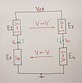
Voltage diagram subtractor 1000.jpg 1,000 × 625; 59 KB
-
Voltage diagram summer 1000.jpg 1,000 × 625; 61 KB
-
Voltage diagram v1-to-v 1000.jpg 1,000 × 625; 58 KB
-
Voltage diagram v2-to-v 1000.jpg 1,000 × 625; 59 KB
-
Voltage-driven neg resistor 1000.jpg 1,000 × 708; 101 KB
-
Voltage-driven neg resistor idea 1000.jpg 1,000 × 710; 101 KB
-
Voltage-to-current1.jpg 1,600 × 1,200; 265 KB
-
Voltage-to-voltage.jpg 1,200 × 1,600; 281 KB
-
Where to take output 1000.jpg 1,000 × 702; 62 KB
-
Wilson current mirror a 1000.jpg 1,000 × 1,186; 163 KB
-
Wilson current mirror b 1000.jpg 1,000 × 1,186; 152 KB
-
Wilson current mirror reversed a 1000.jpg 1,000 × 1,191; 160 KB


