Category:Operational amplifiers
Jump to navigation
Jump to search
high-gain voltage amplifier with a differential input  | |||||
| Upload media | |||||
| Subclass of | |||||
|---|---|---|---|---|---|
| Different from | |||||
| |||||
Subcategories
This category has the following 12 subcategories, out of 12 total.
- SVG operational amplifiers (44 F)
C
D
- Driven guard (7 F)
G
- Gyrators (25 F)
I
- Instrumentation amplifiers (11 F)
- Integrators (15 F)
O
- Op-amp inverting amplifiers (8 F)
- Op-amp non-inverting amplifiers (12 F)
T
V
Media in category "Operational amplifiers"
The following 118 files are in this category, out of 118 total.
-
 0d9c66264ec0102ba2f7c497b0d2eccjyyyy89adcee3a.svg 299 × 34; 8 KB
-
 680px no-feedback model.png 677 × 145; 3 KB
-
 A Magnetic Flux Loop.png 372 × 311; 11 KB
-
 Activefilter.jpg 2,592 × 960; 234 KB
-
 Amplificatore operazionale.svg 183 × 151; 28 KB
-
 Ampliop-courbe.png 328 × 196; 2 KB
-
 Ampliop-courbe.svg 750 × 500; 8 KB
-
 Analóg különbségképző.jpg 312 × 223; 8 KB
-
 Analóg összegző.jpg 393 × 241; 9 KB
-
 AOP dynamic model.png 520 × 240; 7 KB
-
 Bandwidth comparison.JPG 649 × 281; 24 KB
-
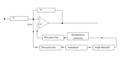
 Blok šema operacionog pojačavača.png 800 × 240; 28 KB
-
 Buffer laga med operasjonsforsterkar.png 800 × 332; 15 KB
-

-
 Cap dif volt comp graph 1000.jpg 1,000 × 713; 103 KB
-
 Cap int volt comp graph 1000.jpg 1,000 × 708; 105 KB
-
 Cc-opamp-diamond transistor and OpAmp symbol.svg 145 × 210; 9 KB
-
 CC-OPV.svg 177 × 106; 10 KB
-
 Clevercard TLV2741.jpg 1,024 × 768; 179 KB
-
 Compensation aop.svg 600 × 480; 12 KB
-
 Compensation ofset.PNG 722 × 365; 7 KB
-
 Convertitore Digitale-Analogico a reti pesate a 4 bit.svg 311 × 190; 39 KB
-
 Convertitore Digitale-Analogico a reti pesate a 8 bit.svg 506 × 402; 72 KB
-
 Diagram of a dominant pole compensated open loop Op-Amp.jpg 4,608 × 1,904; 954 KB
-
 Differenciáló alapkapcsolás.jpg 312 × 246; 7 KB
-
 Differential signal fed into a differential amplifier.svg 512 × 219; 909 bytes
-
 Diode limiter 1000.jpg 1,000 × 714; 25 KB
-
 DMT OpV 2.png 222 × 156; 8 KB
-
 Drivenguard amplifier with negative gain.svg 550 × 500; 25 KB
-
 Drivenguard Voltage buffer.svg 550 × 425; 39 KB
-
 Drivenguard with amplification.svg 550 × 500; 23 KB
-
 Error-amplifier inner.svg 525 × 400; 8 KB
-
 Frequency characteristics operational amplifier.png 583 × 312; 8 KB
-
 Frequency dependent negative resistor.png 6,456 × 3,625; 301 KB
-
 Frequency response in Dominant Pole compensation.jpg 4,437 × 3,123; 1.51 MB
-
 Fully diff amp 1000.jpg 1,000 × 1,177; 103 KB
-
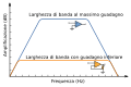 Gain-bandwidth product-it.svg 412 × 272; 22 KB
-
 Gain-bandwidth product.svg 412 × 272; 26 KB
-
 Generalized Impedance Converter-Temes.png 5,975 × 3,300; 258 KB
-
 Generalized Impedance Converter-Wait.png 6,181 × 3,600; 289 KB
-

-
 Gyrator-Temes.png 5,850 × 3,300; 229 KB
-
 Hiszterézises komparátor.jpg 312 × 246; 7 KB
-
 HP respons.png 800 × 384; 26 KB
-
 Ideell operasjonsforsterkar.png 717 × 422; 6 KB
-
 Ikkjeinverterande operasjonsforsterkar.png 800 × 489; 19 KB
-
 Ind int volt comp graph 1000.jpg 1,000 × 708; 101 KB
-
 Input and Output offset voltage of an OPV.png 720 × 818; 22 KB
-
 IntegDeriv.jpg 469 × 141; 20 KB
-
 Integráló alapkapcsolás.jpg 312 × 246; 7 KB
-
 Inv ampl graph volt comp 1000.jpg 1,000 × 712; 104 KB
-
 Inverterande operassjonsforsterkar.png 800 × 360; 16 KB
-
 Invertáló alapkapcsolás.jpg 312 × 246; 6 KB
-
 K2-w Vacuum Tube Op-amp.jpg 546 × 1,086; 109 KB
-
 K2-W.jpg 1,360 × 2,552; 240 KB
-
 LH0021CK.jpg 1,000 × 1,500; 285 KB
-
 Linear inic 0a 1000.jpg 1,000 × 828; 117 KB
-
 Linear inic 1a 1000.jpg 1,000 × 831; 124 KB
-
 Linear inic 1a.jpg 2,868 × 2,376; 1,004 KB
-
 Linear inic 2a 1000.jpg 1,000 × 829; 108 KB
-
 Linear inic 3a 1000.jpg 1,000 × 828; 107 KB
-
 Linear inic 4a 1000.jpg 1,000 × 828; 109 KB
-
 Linear inic 5a 1000.jpg 1,000 × 829; 113 KB
-
 Linear inic 6a 1000.jpg 1,000 × 829; 112 KB
-
 Linear inic 7a 1000.jpg 1,000 × 825; 114 KB
-
 Linear inic 8a 1000.jpg 1,000 × 830; 112 KB
-
 Linear inic 9a 1000.jpg 1,000 × 833; 112 KB
-
 Linear vnic 0a 1000.jpg 1,000 × 829; 116 KB
-
 Linear vnic 0a.jpg 2,856 × 2,372; 972 KB
-
 Linear vnic 1a 1000.jpg 1,000 × 828; 119 KB
-
 Log volt comp graph 1000.jpg 1,000 × 713; 105 KB
-
 LP respons.png 800 × 350; 25 KB
-
 MAA501 OPA.jpg 573 × 688; 184 KB
-
 Neutralizing stray capacitance.jpg 560 × 520; 74 KB
-
 Normsymbol OPV.svg 450 × 600; 7 KB
-

-
 Op-amp follower screen 65a 1000.jpg 1,000 × 730; 52 KB
-
 Op-amp ideale interno.PNG 467 × 314; 6 KB
-
 Op-amp symbol-2.svg 200 × 170; 12 KB
-
 Op-amp transfer char 65a 1000.jpg 1,000 × 742; 23 KB
-
 Opamp blok.PNG 560 × 380; 39 KB
-
 OpAmp-w o Supply-symbol.svg 252 × 385; 5 KB
-
 OpAmp.png 132 × 62; 1 KB
-
 Opampcomparator.svg 945 × 351; 6 KB
-
 OpAmpDerivator2no.png 800 × 357; 19 KB
-
 OpAmpDerivatorr.png 800 × 389; 20 KB
-
 OpAmpIntegrator.png 700 × 400; 18 KB
-
 OpAmpIntegrator2no.png 1,244 × 711; 8 KB
-
 OpAmpModel.png 285 × 131; 3 KB
-
 Opamppinouts.png 150 × 120; 540 bytes
-
 Opeamp.jpg 1,221 × 900; 80 KB
-
 Operac zosilnovac.png 235 × 181; 3 KB
-
 Operational amplifier with non-ideal output resistance.png 303 × 211; 2 KB
-
 OpV CC.png 222 × 156; 6 KB
-
 OpV CV.png 222 × 156; 6 KB
-
 OpV VC.png 217 × 156; 6 KB
-
 OpV VV.png 217 × 156; 6 KB
-
 OpV.png 219 × 170; 6 KB
-
 OpV.svg 206 × 159; 15 KB
-
 Par summer current 1000.jpg 1,000 × 708; 48 KB
-
 Par summer visualized 1000.jpg 1,000 × 676; 60 KB
-
 Par summer voltage 1000.jpg 1,000 × 700; 51 KB
-
 Sensibilitat i Corba de calibració.jpg 488 × 360; 26 KB
-
 Spannung am Integrierer.png 236 × 213; 9 KB
-
 Spannung am Mittelwertbilder.png 236 × 317; 11 KB
-
 Summasjonsforsterkar 2 inng.png 800 × 314; 19 KB
-
 Summasjonsforsterkar N inng.png 800 × 419; 31 KB
-
 Tensione ingresso-uscita di un amplificatore non invertente.jpg 4,000 × 3,000; 3.45 MB
-
 TF after Dominant pole compensation.jpg 3,387 × 3,712; 1.46 MB
-
 Transfer function of an improved super diode.png 284 × 223; 4 KB
-
 TriggerSchmitt CMP.png 250 × 987; 53 KB
-
 Uncompensated Transfer Function of open loop Op-Amp.jpg 2,971 × 1,331; 448 KB
-
 Uscitapreamp.png 1,217 × 279; 12 KB
-
 V-to-i op-amp current source 1000.jpg 1,000 × 707; 70 KB
-
 VC-OPV OTA.svg 170 × 106; 9 KB
-
 VC-OPV.svg 177 × 106; 9 KB
-
 Voltage diagram v2-to-v 1000.jpg 1,000 × 625; 59 KB
-
 VV-OPV.svg 177 × 106; 7 KB


.png)


