Category:Process flow diagrams
Перейти до навігації
Перейти до пошуку
- (de) Fließbild
- (en) Process flow diagram
- (es) Diagrama de flujo
- (fr) schéma de procédé
- (he) תזרים תהליך
сторінка значень у проєкті Вікімедіа | |||||
| Завантажити медіафайл | |||||
| Є підкласом | |||||
|---|---|---|---|---|---|
| |||||
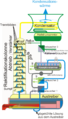
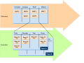
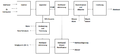
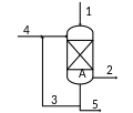
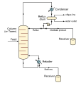
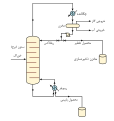
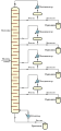
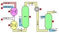
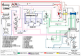
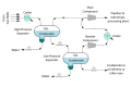
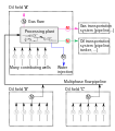
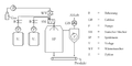
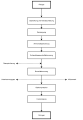
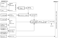
A process flow diagram (PFD) is a diagram commonly used in chemical and process engineering to indicate the general flow of plant processes and equipment.
Підкатегорії
Показано 2 підкатегорії з 2.
C
P
Сторінки в категорії «Process flow diagrams»
Показано 1 сторінку цієї категорії (із 1).
Файли в категорії «Process flow diagrams»
Показано 182 файли цієї категорії (із 182).
-
 A complex procedure composed of simpler procedures.svg 512 × 542; 34 КБ
-
 Absorption chiller scheme.svg 744 × 744; 53 КБ
-
 Absorptionskuehlung Abb 2.jpg 1586 × 818; 109 КБ
-
 AKM.png 510 × 891; 260 КБ
-
 Aliran Proses Untuk Pembuatan Insulin.png 1456 × 746; 57 КБ
-
 AmineTreating.png 383 × 335; 5 КБ
-
 Aminwäsche.jpg 8660 × 5454; 1,18 МБ
-
 Anime production it.png 2200 × 362; 87 КБ
-
 Back Mixing and Digester.png 999 × 753; 47 КБ
-
 Beyond User Stories - MMFs (Minimally Marketable Features).svg 512 × 384; 134 КБ
-
 Binary sensor model.svg 850 × 567; 46 КБ
-
 Biodieselblockdiagramm nach van Gerpen.png 1285 × 576; 35 КБ
-
 BiodieselBlockdiagramm.svg 965 × 235; 6 КБ
-
 Biorieselbettreaktor nach VDI 3478-2.svg 640 × 545; 19 КБ
-
 Biowaescher nach VDI 3478-1.svg 788 × 558; 34 КБ
-
 BtL-Verfahrensschema.svg 744 × 1052; 25 КБ
-
 Carbon black production.svg 953 × 447; 292 КБ
-

-
 Chaine conditionnement bacpro mei 2009.svg 662 × 616; 492 КБ
-
 ChemSepProcDiagram.png 692 × 508; 3 КБ
-
 ChemSepProcDiagram.svg 658 × 510; 5 КБ
-
 Claus Sulfur Recovery.png 507 × 243; 10 КБ
-
 Claus-Anlage.jpg 960 × 720; 58 КБ
-
 Claus-Prozess.png 1633 × 597; 71 КБ
-
 ClausPlt.JPG 800 × 449; 51 КБ
-
 Colloidal silica preparations.svg 700 × 450; 23 КБ
-
 Compensatore idraulico.svg 1100 × 650; 16 КБ
-
 Continuous Binary Fractional Distillation EN.svg 664 × 699; 15 КБ
-
 Continuous Binary Fractional Distillation fa.svg 664 × 699; 23 КБ
-
 Continuous Binary Fractional Distillation-es.png 1800 × 2646; 311 КБ
-
 Continuous Binary Fractional Distillation.PNG 1736 × 2552; 43 КБ
-
 Continuous Fractional Distillation EN.svg 675 × 1273; 18 КБ
-
 Continuous Fractional Distillation ru.svg 542 × 1155; 3 КБ
-
 Continuous Fractional Distillation.PNG 300 × 490; 11 КБ
-
 ConvKeroMerox.png 453 × 357; 14 КБ
-
 ConvLPGMerox.png 559 × 529; 27 КБ
-
 Crude Oil Distillation Unit.png 505 × 445; 24 КБ
-
 Dampfreformierung (2).svg 932 × 488; 97 КБ
-
 Dampfreformierung-Nummern.svg 1920 × 1080; 6 КБ
-
 Dampfreformierung.svg 1900 × 1100; 6 КБ
-
 Delayed Coker.png 596 × 488; 20 КБ
-
 Demethanizer.PNG 340 × 364; 12 КБ
-
 Destilery.gif 592 × 419; 15 КБ
-
 Diagram obrazujący obieg przesyłek w systemie EZD.jpg 819 × 540; 114 КБ
-
 Distillation sous vide.JPG 493 × 336; 16 КБ
-
 DruckwechselRektifikation.svg 744 × 524; 278 КБ
-
 Düngerherstellung.svg 1600 × 2000; 73 КБ
-
 Electrolysis.JPG 826 × 384; 24 КБ
-
 Electrumlab Gasbox.jpg 3200 × 2000; 2,25 МБ
-
 Encebado de bombas2.png 890 × 512; 108 КБ
-

-
 Engineering-Chemical-Process-PFD-Crude-Oil-Distillation-Unit.png 1027 × 726; 82 КБ
-
 Ethylene oxide production plant.svg 1300 × 850; 120 КБ
-
 Fabrication curly.jpg 574 × 464; 44 КБ
-
 Feed Mix.png 865 × 574; 21 КБ
-
 Fliessbild01.png 993 × 678; 153 КБ
-
 Fliessbild02.png 907 × 593; 98 КБ
-
 Fliessbild03.png 969 × 646; 103 КБ
-
 Fließschema Syntheseprozess Tetraethylblei.svg 487 × 637; 247 КБ
-
 Flowsheet for production of biodiesel in aspen plus.png 1024 × 438; 55 КБ
-
 Flujograma proceso gestion contractual.JPG 585 × 546; 62 КБ
-
 Fonctionnement d'un terminal méthanier.jpg 985 × 692; 53 КБ
-
 Gas black process.svg 780 × 390; 120 КБ
-
 Gaswäscher allgemein.jpg 1168 × 681; 60 КБ
-
 Geib-Spevack.svg 767 × 862; 221 КБ
-
 Ginplant.jpg 550 × 366; 51 КБ
-
 Girdler.JPG 400 × 400; 21 КБ
-
 Girdler.svg 870 × 1000; 6 КБ
-
 Gleichstromaustauscher.svg 921 × 1506; 31 КБ
-
 GP1 ProcessSchematic.png 1559 × 741; 269 КБ
-
 Grate-kiln flöde.jpg 813 × 256; 34 КБ
-
 GTL process.GIF 1138 × 1058; 25 КБ
-
 Haber process.png 300 × 230; 4 КБ
-
 Haber-Bosch it.svg 2517 × 866; 115 КБ
-
 Haber-Bosch-En.svg 512 × 154; 881 КБ
-
 Haber-Bosch-es.svg 2517 × 866; 117 КБ
-
 Haber-Bosch-fr.svg 2517 × 866; 117 КБ
-
 Haber-Bosch-mk.svg 512 × 154; 1,12 МБ
-
 Haber-Bosch-Nummern.svg 3700 × 1200; 17 КБ
-
 Haber-Bosch-tr.svg 512 × 154; 873 КБ
-
 Haber-Bosch.svg 3800 × 1200; 12 КБ
-
 Hall-heroult-kk-2008-12-31.png 585 × 512; 32 КБ
-
 HDS Flow.png 546 × 332; 18 КБ
-
 Herstellung Zement Beton.svg 744 × 1052; 22 КБ
-
 HFQ Technology Process Steps.jpg 2103 × 1024; 499 КБ
-
 Hochofen 1965-2.png 4095 × 2817; 1,93 МБ
-
 Hochofen 1965.png 5892 × 4052; 1,45 МБ
-
 Hydrodesulfurierung Prozess-ar.png 1274 × 458; 51 КБ
-
 Hydrogen from natural gas schematics.jpg 913 × 601; 269 КБ
-
 Hydrolysis of cellulose (Hägglund-Bergius).svg 1817 × 469; 907 КБ
-
 IGCC diagram fr.svg 1052 × 744; 157 КБ
-
 IGCC diagram.svg 975 × 538; 191 КБ
-
 Impianto di produzione di ossido di etilene.png 1300 × 850; 137 КБ
-
 Impianto di produzione di ossido di etilene.svg 1300 × 850; 166 КБ
-
 ITmk3 Process diagram.svg 2385 × 1331; 174 КБ
-
 Kaatsufujouhou-2.JPG 720 × 540; 36 КБ
-
 Kaatsufujouhou.JPG 720 × 540; 35 КБ
-
 Kalkherstellung gross.png 1065 × 498; 100 КБ
-
 Kalkherstellung.svg 800 × 600; 96 КБ
-
 Kalkherstellungv2.png 1300 × 913; 176 КБ
-
 KalkherstellungV2.svg 800 × 600; 100 КБ
-
 Koepchenwerk DSC8586.jpg 6000 × 4000; 14,19 МБ
-
 Kontinuierliche fraktionierende binäre Destillation DE.svg 664 × 699; 17 КБ
-
 Kontinuierliche fraktionierende Destillation DE.svg 675 × 1273; 18 КБ
-
 Krupp-Renn Process diagram.svg 716 × 412; 56 КБ
-
-
 LNG Process Ar.png 662 × 1002; 31 КБ
-
 Melkeproduksjon.svg 612 × 792; 203 КБ
-
 Metodo contacto pirita.svg 1052 × 744; 417 КБ
-
 Midrex Process diagram.svg 557 × 396; 91 КБ
-
 MLCC-Manufacturing-Process.png 960 × 720; 177 КБ
-
 NatGasProcessing ar.svg 744 × 524; 45 КБ
-
 NatGasProcessing-es.svg 744 × 524; 57 КБ
-
 NatGasProcessing.png 584 × 465; 22 КБ
-
 NatGasProcessing.svg 744 × 524; 38 КБ
-
 NaturalGasCondensate ar.svg 1500 × 1000; 216 КБ
-
 NaturalGasCondensate en.svg 1500 × 1000; 31 КБ
-
 NaturalGasCondensate.png 296 × 200; 7 КБ
-
 Nixtamal.jpg 360 × 694; 32 КБ
-
 Oil distillation tower BlockDiagram NT.PNG 800 × 720; 57 КБ
-
 Oil field flow metering.svg 750 × 850; 94 КБ
-
 Ostwald schem.svg 2463 × 1510; 235 КБ
-
 Oxygen Reactor.png 779 × 481; 23 КБ
-
 P&ID drawing template.jpg 1180 × 610; 140 КБ
-
 Petroleum distillation.png 950 × 564; 18 КБ
-
 PGSS-Verfahren Brandin.png 1134 × 569; 83 КБ
-
 Phosphor production (bs).svg 925 × 660; 25 КБ
-
 Phosphor production (de).svg 925 × 660; 13 КБ
-
 Phosphor production (en)-mr.svg 925 × 660; 30 КБ
-
 Phosphor production (en).svg 925 × 660; 13 КБ
-
 Phosphor production-te.svg 925 × 660; 25 КБ
-
 Pipeline cross connection.svg 540 × 270; 64 КБ
-
 Platform Purification of Antibodies using Protein A.jpg 276 × 957; 104 КБ
-
 Polietilene - produzione di HDPE e LLDPE.svg 1052 × 900; 194 КБ
-
 Polyvinyl chloride (PVC) production from suspension polymerization.svg 1128 × 1262; 46 КБ
-
 Precedence Table2.jpg 2443 × 480; 159 КБ
-
 Process diagramm crude gas.svg 1276 × 1843; 9 КБ
-
 Process of electronic Voting.png 685 × 801; 130 КБ
-
 Process of Production of Soy Sauce.png 2710 × 1661; 498 КБ
-
 Produktionsablauf Metallhüttenwerk Lübeck.png 5892 × 4052; 1,23 МБ
-
 ProjectTinkertoy 031.jpg 6068 × 1893; 2,43 МБ
-
 ProjectTinkertoy 032.jpg 5858 × 2224; 2,55 МБ
-
 ProjectTinkertoy 033.jpg 5873 × 2765; 2,16 МБ
-
 ProjectTinkertoy 036.jpg 7751 × 2795; 9,19 МБ
-
 ProjectTinkertoy 037.jpg 5513 × 3532; 9,26 МБ
-
 ProjectTinkertoy 038.jpg 5948 × 3427; 5,04 МБ
-
 Raffinerie.PNG 1712 × 928; 32 КБ
-
 Ress.JPG 438 × 220; 15 КБ
-
 Schem techn KClO3.svg 2688 × 1242; 229 КБ
-
 Schema bioolej rychla pyrolyza.png 654 × 476; 12 КБ
-
 Schema InstantKaffee.svg 415 × 748; 124 КБ
-
 Schematisches Verfahrenfließbild des Zweidruckverfahrens.svg 1140 × 764; 69 КБ
-
 SchemeLOX.jpg 2126 × 1417; 304 КБ
-
 Schmieröltankentlüftung.svg 600 × 500; 19 КБ
-
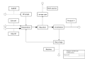 Schéma bloc1.svg 650 × 450; 37 КБ
-
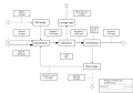 Schéma bloc2.svg 650 × 450; 47 КБ
-
 Shema KP.JPG 1213 × 644; 67 КБ
-
 Siloreinigung1500x800.png 1500 × 851; 200 КБ
-
 Slaked lime production (example).svg 1175 × 1185; 47 КБ
-
 Soap and Detergent manufacturing process 03.png 2000 × 1618; 261 КБ
-
 Sodium hypochlorite process.png 881 × 346; 17 КБ
-
 Steam cracking.svg 1000 × 600; 25 КБ
-
 Syngas Products.svg 1160 × 475; 6 КБ
-
 Synthesis SiO2 de.svg 558 × 556; 63 КБ
-

-

-
 Tie Guan Yin processing chart zh.GIF 614 × 374; 10 КБ
-
 Total Reflux.png 217 × 319; 7 КБ
-
 TPSSimpleSchematic.jpg 872 × 380; 43 КБ
-
 Variation-of-process-flow-diagram.jpg 480 × 363; 37 КБ
-
 Veresterung2.jpg 523 × 535; 23 КБ
-
 Verfahren zur Schwefelsäureherstellung.svg 1470 × 957; 50 КБ
-
 Verfahrensfließschema Zweidruckverfahren THF-Wasser.svg 1091 × 756; 89 КБ
-
 Verfahrensschema Luisenhall.svg 628 × 1003; 24 КБ
-
 Verfahrensschema SalineLuisenhall.svg 628 × 1003; 42 КБ
-
 Vergaserkraftwerk.svg 961 × 515; 155 КБ
-
 Water fuel cell circuit.png 913 × 552; 79 КБ
-
 Water System Validation Process Flow.jpg 953 × 646; 156 КБ
-
 Well test separator.svg 1500 × 1000; 40 КБ
-
 XMOOC-Learning-Process.jpg 1207 × 460; 103 КБ
-

-
 常圧蒸留(ブロックダイアグラム) J.PNG 1000 × 720; 88 КБ


.svg)


.png)


.svg)


_elegy_folyamatos_frakcion%C3%A1ldesztill%C3%A1ci%C3%B3ja_hu.PNG)


.svg)
.svg)
-mr.svg)
.svg)


_production_from_suspension_polymerization.svg)


.svg)


.png)
.png)


_J.PNG)
.svg)