Category:Programmable logic controller
Jump to navigation
Jump to search
digital computer used for automation of electromechanical processes | |||||
| Upload media | |||||
| Subclass of | |||||
|---|---|---|---|---|---|
| |||||
Subcategories
This category has the following 11 subcategories, out of 11 total.
A
- Allen-Bradley PLCs (5 F)
F
- Function block diagrams (13 F)
H
- Hitachi D-64-S (3 F)
I
- Introductory PLC Programming (14 F)
L
R
- Regin (5 F)
S
- Sequential function charts (22 F)
- Siemens PLCs (63 F)
- PLC simulators (3 F)
U
- UniPi PLCs (5 F)
Media in category "Programmable logic controller"
The following 116 files are in this category, out of 116 total.
-
A series PLC.jpg 802 × 480; 29 KB
-
Ace-eace-micro-plc-pcb.png 200 × 200; 45 KB
-
Analog Input module wiring.jpg 805 × 556; 39 KB
-
Analog Output Module connecting to Stepper drive.jpg 1,194 × 555; 54 KB
-
Analog Output Module hardware.jpg 245 × 553; 25 KB
-
Analog Output module wiring.jpg 566 × 534; 38 KB
-
Automate industriel WAGO pour un système de monitoring en industrie pharmaceutique.jpg 4,912 × 3,264; 7.89 MB
-
Automate siemens codeur analyseur de trame.JPG 1,600 × 1,200; 240 KB
-
B&R Box PC.jpg 2,381 × 3,222; 1.41 MB
-
B1z-14MR.jpg 410 × 502; 30 KB
-
Beckhoff-BC9120-with-IO.jpg 1,776 × 1,400; 316 KB
-
BMA Automation Allen Bradley PLC 3.JPG 1,620 × 1,080; 361 KB
-
Control-panel-plc.jpg 720 × 960; 73 KB
-
Controllino mini.jpg 3,381 × 2,536; 3.09 MB
-
DCS DeltaV.png 708 × 818; 182 KB
-
Delta Plc Cpu.jpg 500 × 500; 20 KB
-
Delta PLC CPU.jpg 500 × 500; 21 KB
-
Delta PLC DVP CPU DVP60ES200T.jpg 500 × 500; 22 KB
-
Delta Plc DVP Series CPU.jpg 500 × 500; 19 KB
-
Delta Plc.jpg 366 × 508; 29 KB
-
Digital Output Module G4Q-TR4B,EXP.jpg 500 × 500; 23 KB
-
Dornbirn-Montfortstraße-Moeller PS4-141-MM1-01ASD.jpg 3,111 × 1,392; 274 KB
-
Dornbirn-Technische Alternative-UVR1611-01ASD.png 3,117 × 1,411; 4.01 MB
-
Drum roller.jpg 342 × 249; 27 KB
-
Dual-redundant-configurable hybrid PLC intelligent RTU.jpg 2,000 × 1,312; 1.28 MB
-
Embedded-PC Beckhoff CX1020.jpg 700 × 500; 130 KB
-
FANUC PLC.jpg 2,272 × 1,704; 1.87 MB
-
FCN-RTU.jpg 2,496 × 1,664; 2.08 MB
-
Freelance AC 700F Controller.jpg 267 × 195; 10 KB
-
Freelance AC 800F Controller.jpg 290 × 281; 11 KB
-
FX3U-4DA.jpg 500 × 500; 20 KB
-
Graphical Controller.png 301 × 338; 101 KB
-
Idberzsenyi.jpg 698 × 990; 186 KB
-
LogFøl.PNG 622 × 373; 10 KB
-
LPA512 side.jpg 659 × 351; 27 KB
-
Mini-SPS STG500.jpg 630 × 633; 59 KB
-
MITSIBISHI PLC 04.png 1,000 × 1,300; 1.96 MB
-
MITSIBISHI PLC Panel.jpg 3,264 × 2,448; 3.83 MB
-
MITSUBISHI IO modules 2.png 1,360 × 1,230; 2.32 MB
-
MITSUBISHI IO modules.png 2,400 × 470; 1.74 MB
-
Mitsubishi Plc Cpu.jpg 500 × 500; 14 KB
-
Mitsubishi PLC Fx3u-4AD-PT-ADP.jpg 500 × 500; 20 KB
-
Mitsubushi PLC FX3g.jpg 500 × 500; 22 KB
-
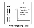
Non Retentive Timer PLC.jpg 411 × 341; 23 KB
-
Normally Open (NO) Contact ladder logic.jpg 326 × 203; 14 KB
-
NPN standard for Sensor.jpg 463 × 193; 16 KB
-
OFF Delay timer PLC.jpg 403 × 307; 20 KB
-
Optical sensor NPN 24VDC.jpg 249 × 192; 17 KB
-
Output Coil ladder logic.jpg 272 × 153; 12 KB
-
PACs on io racks.jpg 356 × 317; 132 KB
-
Paineldeclp.jpg 2,000 × 1,849; 646 KB
-
PLC 8 point Input module sink and source.jpg 306 × 581; 22 KB
-
PLC Block Diagram.jpg 940 × 624; 51 KB
-
Plc control panel.JPG 566 × 555; 35 KB
-
PLC Control Panel.png 428 × 670; 375 KB
-
PLC Digital Input Output Module.jpg 500 × 500; 13 KB
-
PLC Hardware.JPG 838 × 526; 42 KB
-
PLC indgang.png 576 × 422; 7 KB
-
PLC Input Module wiring sink and source.jpg 548 × 533; 27 KB
-
PLC input source wiring.jpg 519 × 539; 27 KB
-
PLC Input type Sourcing.jpg 590 × 490; 28 KB
-
PLC inst 2.png 625 × 573; 8 KB
-
Plc intro-15.svg 744 × 1,052; 68 KB
-
PLC LEARNING ALSO - 2.png 1,002 × 400; 15 KB
-
PLC Output module 8 point relay hardware.jpg 311 × 560; 24 KB
-
PLC Output module 8 point sinking harware.jpg 241 × 509; 22 KB
-
PLC Output module 8 point sourcing hardware.jpg 237 × 524; 23 KB
-
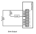
PLC output module sink wiring.jpg 544 × 526; 30 KB
-
PLC Relay module Internal circuit.jpg 638 × 402; 23 KB
-
PLC sinking input Internal circuit.jpg 432 × 387; 26 KB
-
PLC source output Internal circuit.jpg 531 × 412; 25 KB
-
PLC source output module wiring.jpg 555 × 497; 28 KB
-
PLC sourcing input Internal circuit.jpg 465 × 420; 26 KB
-
PLC structure.JPG 1,170 × 771; 73 KB
-
PLC udgang.png 576 × 608; 11 KB
-
PLC udgang2.png 569 × 553; 9 KB
-
PLC udgang3.png 576 × 542; 10 KB
-
PLC udgang4.png 581 × 574; 10 KB
-
PLC wire.png 534 × 469; 9 KB
-
PLCDP.jpg 1,280 × 733; 120 KB
-
PLC外觀.JPG 550 × 263; 30 KB
-
PNP standard for Sensor.jpg 432 × 192; 15 KB
-
Program1 (7).jpg 338 × 104; 7 KB
-
Programmable logic controller.jpg 1,646 × 830; 409 KB
-
Relæ.png 802 × 758; 90 KB
-
Relæ2.png 1,146 × 902; 12 KB
-
Remote Input Outputs IO.png 364 × 210; 65 KB
-
Remote Terminal Unit Modular.jpg 1,616 × 1,503; 592 KB
-
Retentive timer PLC.jpg 375 × 327; 19 KB
-
S5 life.JPG 664 × 299; 43 KB
-
Schleicher Electronic Pro Numeric XCI 1200.jpg 2,064 × 3,500; 3.23 MB
-
Siemens Microbox PC.jpg 4,608 × 2,592; 3.23 MB
-
SIEMENS RLU222+SEH62.1.JPG 2,048 × 1,536; 690 KB
-
Sink output Internal circuit.jpg 483 × 392; 22 KB
-
Sinking Output PLC.jpg 610 × 451; 28 KB
-
Sinking type PLC input.jpg 566 × 456; 28 KB
-
Sourcing Output PLC.jpg 601 × 437; 28 KB
-
Spsö1.PNG 842 × 621; 14 KB
-
StxLadder-v1.4.9.png 1,918 × 1,032; 193 KB
-
Subdriver foto1.jpg 590 × 786; 59 KB
-
Switch and LED PLC connection address.jpg 782 × 428; 27 KB
-
Unitronics check sum calc.svg 1,279 × 1,771; 127 KB
-
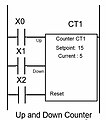
Up and Down counter PLC.jpg 365 × 412; 24 KB
-
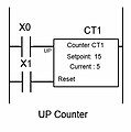
UpCounter PLC.jpg 368 × 371; 21 KB
-
V2000 IP Controller.jpg 314 × 251; 50 KB
-
Voltage divider for PLC analig Input module.jpg 765 × 580; 41 KB
-
WIN 20150420 091711.JPG 1,280 × 720; 166 KB
-
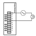
Wiring a bulb to a PLC module hardware.jpg 543 × 532; 23 KB
-
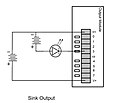
Wiring LED to PLC Sink Output module.jpg 595 × 513; 30 KB
-
Wiring LED to PLC Source Output module.jpg 606 × 521; 30 KB
-
Wiring PLC relay module hardware.jpg 452 × 492; 26 KB
-
Wiring Potentiometer to PLC analog Input module.jpg 848 × 568; 43 KB
-
Wiring solonoid valve to PLC Source Output module.jpg 666 × 530; 35 KB
-
БАЗИС(товарный знак).jpg 740 × 160; 32 KB


