File:Early Lecher line.png
Archivo original (985 × 503 píxeles; tamaño de archivo: 58 kB; tipo MIME: image/png)
Leyendas
Leyendas
Resumen
[editar]| Descripción |
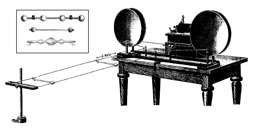
English: Drawing of an early demonstration Lecher line apparatus, from a 1902 catalog of scientific equipment. It is very similar to the first Lecher line built by Austrian physicist Ernst Lecher in 1888. A Lecher line is a pair of parallel wires or rods that were used to measure the wavelength of radio waves. In this example, the radio waves are generated by the Hertzian spark-gap oacillator (right) and sent down the Lecher line, the pair of parallel wires to the left. The Lecher line forms a length of balanced transmission line, along which the waves travel at the speed of light. At the left end of the line the two wires are connected together. This short-circuit termination reflects the waves back up the line toward the transmitter. The outgoing and reflected waves interfere with each other, creating a series of standing waves on the line. The voltage across the line goes to zero at nodes that occur at regular intervals of one-half wavelength (λ/2) from the end of the line. The distance between two nodes is measured and multiplied by two to get the wavelength λ. Since the waves travel at the speed of light, c, the frequency of the waves f can be calculated:
To find the location of the nodes, a Geissler tube, similar to a small neon light, is suspended from hooks across the line and slid up and down the line. The high voltage waves cause it to glow. At the nodes the voltage goes to zero so the Geissler tube goes out. The inset (top left) shows the type of Geissler tubes that were used with Lecher lines. The Hertzian oscillator (right) generated radio waves in the UHF range, with wavelengths of a few meters, so a 6 meter Lecher line was used (the length is truncated in this drawing). The oscillator consists of an induction coil that generates a high voltage that jumps across a spark gap (center) many times per second. The two sides of the spark gap are coupled to the Lecher line through two parallel-plate capacitors (circles). The energy stored in the capacitors is discharged into the line during each spark, generating a brief oscillating radio wave (damped wave) that decays to zero. The symmetrical balanced circuit ensures that equal and opposite voltage waves are induced in each wire. Alterations to image: extended the length of the Lecher line, which was misleadingly shortened to several inches long in the original drawing to save space. Added inset showing closeup of Geissler tubes from nearby drawing in same source.Deutsch: Dieses Stehwellenmessgerät wurde 1888 vom Physiker Ernst Lecher entwickelt, um Wellenlängen und Frequenzen zu messen. Die Abbildung stammt aus einem Katalog für wissenschaftliche Laborausrüstung aus dem Jahr 1904 und ist für Wellenlängen um 1 m geeignet. |
| Fecha | |
| Fuente | Downloaded 2010-11-16 from Physikalische Apparate, Preisliste No. 18 (1904) Ferdinand Ernecke, Berlin, Germany, p.304, fig. 8800 in Instruments for Science collection, Smithsonian Institution |
| Autor | Desconocido |
| Permiso (Reutilización de este archivo) |
Public domain - it was published at least 106 years ago. |

Licencia
[editar]
|
Esta es una reproducción fotográfica fiel de una obra de arte bidimensional de dominio público. La obra de arte misma se halla en el dominio público por el motivo siguiente:
La postura oficial de la Fundación Wikimedia considera que «las reproducciones fieles de obras de arte bidimensionales de dominio público forman parte del dominio público». Esta reproducción fotográfica, por ende, también se considera de dominio público dentro de los Estados Unidos. Es posible que otras jurisdicciones restrinjan la reutilización de este contenido; consúltese Reutilización de fotografías PD-Art (en inglés) para más detalles. {{PD-Art}} template without license parameter: please specify why the underlying work is public domain in both the source country and the United States
(Usage: {{PD-Art|1=|deathyear=''year of author's death''|country=''source country''}}, where parameter 1= can be PD-old-auto, PD-old-auto-expired, PD-old-auto-1996, PD-old-100 or similar. See Commons:Multi-license copyright tags for more information.) | ||||
Historial del archivo
Haz clic sobre una fecha y hora para ver el archivo tal como apareció en ese momento.
| Fecha y hora | Miniatura | Dimensiones | Usuario | Comentario | |
|---|---|---|---|---|---|
| actual | 17:44 16 nov 2010 | | 985 × 503 (58 kB) | Chetvorno (discusión | contribs.) | {{Information |Description= {{en|Drawing of early Lecher line apparatus, similar to that used by German physicist Ernst Lecher when he invented the Lecher line in 1888. Used in radio engineering, a Lecher line is a pair of parallel wires or rods that are |
No puedes sobrescribir este archivo.
Usos del archivo
No hay páginas que enlacen a este archivo.
Uso global del archivo
Las wikis siguientes utilizan este archivo:
- Uso en de.wikipedia.org
- Uso en en.wikipedia.org
- Uso en es.wikipedia.org
- Uso en nl.wikipedia.org
- Uso en pl.wikipedia.org