File:Sidelobes en.svg

原始文件 (SVG文件,尺寸为360 × 360像素,文件大小:6 KB)
说明
说明
摘要[编辑]
| 描述 |
Català: Patró de radiació azimutal d'una antena direccional típica, que mostra el lòbul principal, lòbul posterior i lòbuls laterals. La distància des de l'origen mostra la intensitat del senyal (densitat de potència) en funció de l'angle. A causa de la interferència entre les ones de ràdio emeses per diferents parts de l'antena, un patró de radiació d'antena típic té lòbuls, direccions en què la intensitat de la radiació és un màxim local, separats per nulls, direccions en què la radiació és un mínim local o zero. En una antena direccional, el lòbul més gran, que mostra la direcció de la major part de la radiació, s'anomena lòbul principal, que representa la direcció desitjada de la radiació. La resta de la potència s'irradia en lòbuls laterals, normalment representant radiació no desitjada en altres direccions. Moltes antenes emeten un gran senyal en una direcció oposada al lòbul principal; això s'anomena lòbul posterior.
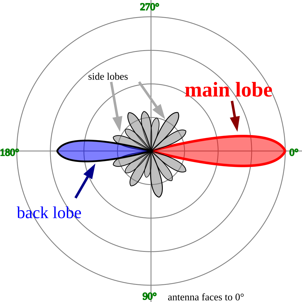
English: Azimuthal radiation pattern of a typical directional antenna, showing main lobe, back lobe and side lobes. The distance from the origin shows the signal strength (power density) as a function of angle. Due to interference between radio waves emitted by different parts of the antenna, a typical antenna radiation pattern has lobes, directions in which the radiation strength is a local maximum, separated by nulls, directions in which radiation is a local minimum or zero. In a directional antenna the largest lobe, showing the direction of most of the radiation, is called the main lobe, which represents the desired direction of the radiation. The rest of the power is radiated in sidelobes, usually representing unwanted radiation in other directions. Many antennas emit a large signal in a direction opposite the main lobe; this is called the backlobe.
Русский: Диаграмма направленности с боковыми лепестками. |
| 日期 | (UTC) |
| 来源 | 自己的作品 |
| 作者 | Timothy Truckle |
| 其他版本 |
File:Sidelobes en.svg has 2 translations.
Other related versions:[]
|


|
This SVG file contains embedded text that can be translated into your language, using any capable SVG editor, text editor or the SVG Translate tool. For more information see: About translating SVG files. |
This file is translated using SVG <switch> elements. All translations are stored in the same file! Learn more.
For most Wikipedia projects, you can embed the file normally (without a To translate the text into your language, you can use the SVG Translate tool. Alternatively, you can download the file to your computer, add your translations using whatever software you're familiar with, and re-upload it with the same name. You will find help in Graphics Lab if you're not sure how to do this. |
许可协议[编辑]

|
已授权您依据自由软件基金会发行的无固定段落及封面封底文字(Invariant Sections, Front-Cover Texts, and Back-Cover Texts)的GNU自由文件许可协议1.2版或任意后续版本的条款,复制、传播和/或修改本文件。该协议的副本请见“GNU Free Documentation License”。 |
- 您可以自由地:
- 共享 – 复制、发行并传播本作品
- 修改 – 改编作品
- 惟须遵守下列条件:
- 署名 – 您必须对作品进行署名,提供授权条款的链接,并说明是否对原始内容进行了更改。您可以用任何合理的方式来署名,但不得以任何方式表明许可人认可您或您的使用。
- 相同方式共享 – 如果您再混合、转换或者基于本作品进行创作,您必须以与原先许可协议相同或相兼容的许可协议分发您贡献的作品。
文件历史
点击某个日期/时间查看对应时刻的文件。
| 日期/时间 | 缩略图 | 大小 | 用户 | 备注 | |
|---|---|---|---|---|---|
| 当前 | 2024年1月21日 (日) 17:03 | | 360 × 360(6 KB) | Manlleus(留言 | 贡献) | File uploaded using svgtranslate tool (https://svgtranslate.toolforge.org/). Added translation for ca. |
| 2012年12月7日 (五) 16:40 |  | 360 × 360(5 KB) | Glrx(留言 | 贡献) | Opposite side lobe changed to back lobe. English version of title. Grammar correction in description. | |
| 2008年6月20日 (五) 07:28 |  | 360 × 360(5 KB) | Timothy Truckle(留言 | 贡献) | spelling correted | |
| 2008年6月20日 (五) 07:27 |  | 360 × 360(5 KB) | Timothy Truckle(留言 | 贡献) | Use of unicode character ° (°) | |
| 2008年6月19日 (四) 20:19 |  | 360 × 360(5 KB) | Timothy Truckle(留言 | 贡献) | Diagramm of antenna side lobes This diagram illustrates how he energy of electro magnetic waves is emitted on an antenna. This diagrams show the line where the energy is less than 3db compared to an iso emitter. | |
| 2008年6月19日 (四) 20:15 |  | 360 × 360(5 KB) | Timothy Truckle(留言 | 贡献) | Diagramm of antenna side lobes This diagram illustrates how he energy of electro magnetic waves is emitted on an antenna. This diagrams show the line where the energy is less than 3db compared to an iso emitter. |
您不可以覆盖此文件。
文件用途
以下8个页面使用本文件:
全域文件用途
以下其他wiki使用此文件:
- ar.wikipedia.org上的用途
- ca.wikipedia.org上的用途
- en.wikipedia.org上的用途
- en.wikiversity.org上的用途
- es.wikipedia.org上的用途
- et.wikipedia.org上的用途
- eu.wikipedia.org上的用途
- fa.wikipedia.org上的用途
- he.wikipedia.org上的用途
- it.wikipedia.org上的用途
- it.wikiversity.org上的用途
- la.wikipedia.org上的用途
- pt.wikipedia.org上的用途
- tr.wikipedia.org上的用途
- uk.wikipedia.org上的用途
- www.wikidata.org上的用途
- zh.wikipedia.org上的用途