File:Diode-IV-Curve.svg
Jump to navigation
Jump to search

Size of this PNG preview of this SVG file: 500 × 300 pixels. Other resolutions: 320 × 192 pixels | 640 × 384 pixels | 1,024 × 614 pixels | 1,280 × 768 pixels | 2,560 × 1,536 pixels.
Original file (SVG file, nominally 500 × 300 pixels, file size: 24 KB)
Captions
Captions
Add a one-line explanation of what this file represents
Summary[edit]
| Description |
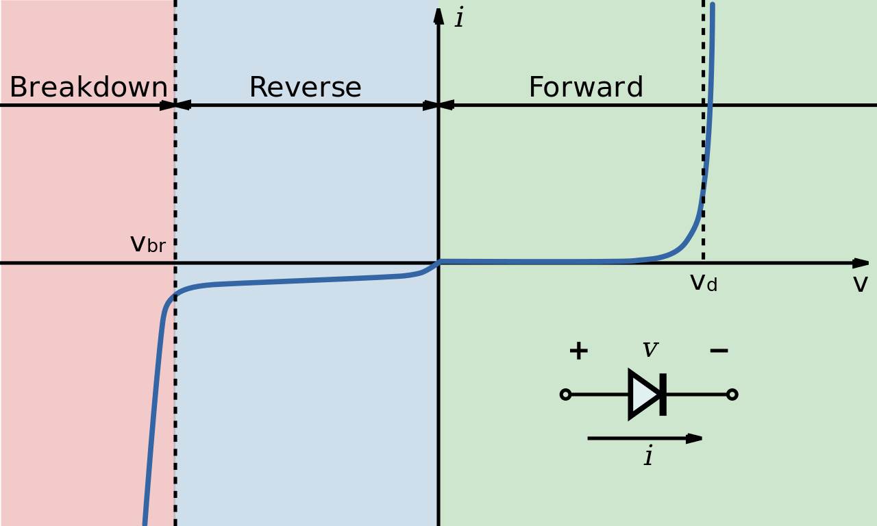
English: Diode I-V diagram. Includes three main areas of operation: breakdown, reverse-biased, and forward-biased. Vbr denotes the breakdown voltage, and Vd denotes the voltage that is typically considered "on" (conducting current).
Note the reverse current scale is finer than the forward current scale: In almost all real devices, the forward current will not be less than the reverse current given the same voltage magnitude.
Русский: Вольт-амперная характеристика полупроводникового диода. Состоит из трёх областей: обратного лавинного пробоя, обратной ветви нормальной работы и прямой ветви. обозначает напряжение начала пробоя, – напряжение включения при прямом смещении. Ось токов при обратном смещении для наглядности многократно растянута. |
| Date | |
| Source | Roughly derived from http://en.wikipedia.org/wiki/File:Rectifier_vi_curve.GIF. Vectorization is own work. |
| Author | H1voltage |
| Other versions |
Derivative works of this file: |


Licensing[edit]
I, the copyright holder of this work, hereby publish it under the following licenses:
This file is licensed under the Creative Commons Attribution-Share Alike 3.0 Unported license.
- You are free:
- to share – to copy, distribute and transmit the work
- to remix – to adapt the work
- Under the following conditions:
- attribution – You must give appropriate credit, provide a link to the license, and indicate if changes were made. You may do so in any reasonable manner, but not in any way that suggests the licensor endorses you or your use.
- share alike – If you remix, transform, or build upon the material, you must distribute your contributions under the same or compatible license as the original.

|
Permission is granted to copy, distribute and/or modify this document under the terms of the GNU Free Documentation License, Version 1.2 or any later version published by the Free Software Foundation; with no Invariant Sections, no Front-Cover Texts, and no Back-Cover Texts. A copy of the license is included in the section entitled GNU Free Documentation License. |
You may select the license of your choice.
File history
Click on a date/time to view the file as it appeared at that time.
| Date/Time | Thumbnail | Dimensions | User | Comment | |
|---|---|---|---|---|---|
| current | 04:05, 22 April 2011 | | 500 × 300 (24 KB) | Hardwigg (talk | contribs) | Made the text a little bigger for easier reading |
| 12:22, 4 April 2009 |  | 500 × 300 (26 KB) | Inductiveload (talk | contribs) | tweaked | |
| 20:34, 31 March 2009 |  | 500 × 300 (26 KB) | Inductiveload (talk | contribs) | modified style slightly to better match other images and render cleanely at 100% zoom without antialiasing. | |
| 04:28, 16 January 2009 |  | 500 × 300 (18 KB) | H1voltage~commonswiki (talk | contribs) | {{Information |Description={{en|1=Diode I-V diagram. Includes three main areas of operation: breakdown, reverse-biased, and forward-biased. Vbr denotes the breakdown voltage, and Von denotes the voltage that is typically considered "on" (conducting curr |
You cannot overwrite this file.
File usage on Commons
The following 5 pages use this file:
File usage on other wikis
The following other wikis use this file:
- Usage on ar.wikipedia.org
- Usage on ba.wikipedia.org
- Usage on bn.wikipedia.org
- Usage on ca.wikipedia.org
- Usage on en.wikipedia.org
- Usage on fa.wikipedia.org
- Usage on fr.wikipedia.org
- Usage on hi.wikipedia.org
- Usage on it.wikipedia.org
- Usage on kk.wikipedia.org
- Usage on no.wikipedia.org
- Usage on pl.wikipedia.org
- Usage on sh.wikipedia.org
- Usage on sl.wikipedia.org
- Usage on sr.wikipedia.org
- Usage on th.wikipedia.org
- Usage on tt.wikipedia.org
- Usage on ur.wikipedia.org
- Usage on zh.wikipedia.org
- Usage on zh.wikiversity.org