Unified Modeling Language

Unified Modeling Language (UML) is a standardized visual specification language for object modeling in the field of software engineering.
Overview[edit]
Unified Modeling Language is a general-purpose modeling language that includes a graphical notation used to create an abstract model of a system, referred to as a UML model. It consists of:
- Structure diagrams: emphasize what things must be in the system being modeled
- Behavior diagrams: emphasize what must happen in the system being modeled
- Interaction diagrams: a subset of behavior diagrams, emphasize the flow of control and data among the things in the system being modeled.

Unified Modeling Language is officially defined at the w:Object Management Group (OMG) by the w:UML metamodel, a w:Meta-Object Facility metamodel (MOF). Like other Meta-Object Facility-based specifications, Unified Modeling Language has allowed software developers to concentrate more on design and architecture.
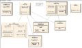
- Collage of types of diagrams


- Separate types of diagrams
-
 A class diagram
 -
 A component diagram
 -
 A composite structure diagram
 -
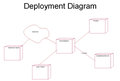 A deployment diagram
 -
 An object diagram
 -
 An activity diagram
 -
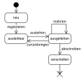 A state diagram
 -
 A use case diagram
 -
 A communication diagram
 -
 An interaction overview diagram
 -
 A sequence diagram


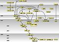
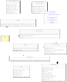
History[edit]
-
 Diagram by Guido Zockoll, 2004
 -
 Diagram by Michael Zapf, 2006
 -
 Diagram by Axel Scheithauer, 2008
 -
 Update by Marcel Douwe Dekker, 2008
 -
 Redraw by Chris828, 2009
 -
 Update by Marcel Douwe Dekker, 2012


Structure diagrams[edit]
Class diagram[edit]
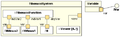
A class diagram describes the structure of a system by showing the system's classes, their attributes, and the relationships between the classes. See Category:Class diagrams


Component diagram[edit]
A component diagram in the Unified Modeling Language depicts how a software system is split up into components and shows the dependencies among these components. See Category:Component diagrams


Composite structure diagram[edit]
Composite structure diagram is describes the internal structure of a class and the collaborations that this structure makes possible. See Category:Composite structure diagrams


Deployment diagram[edit]
A deployment diagram serves to model the hardware used in system implementations, the components deployed on the hardware, and the associations between those components.. See Category:Deployment diagrams


Object diagram[edit]
An object diagram shows a complete or partial view of the structure of a modeled system at a specific time. See Category:Object diagrams

Package diagram[edit]
A package diagram depicts how a system is split up into logical groupings by showing the dependencies among these groupings. See Category:Package diagrams


Behavior diagrams[edit]
Activity diagrams[edit]
An activity diagram In UML represents the business and operational step-by-step workflows of components in a system. An activity diagram shows the overall flow of control. See Category:UML Activity diagrams


State diagram[edit]
A state diagram in UML is a standardized notation to describe many systems, from computer programs to business processes. See Category:UML State diagrams


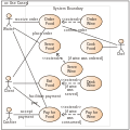
Use case diagram[edit]
A Use Case diagram in Unified Modeling Language shows the functionality provided by a system in terms of actors, their goals represented as use cases, and any dependencies between those use cases. See Category:Use Case diagrams


Interaction diagrams[edit]
Communication diagram[edit]
A Communication diagram models the interactions between objects or parts in terms of sequenced messages. They represent a combination of information taken from Class, Sequence, and Use Case Diagrams describing both the static structure and dynamic behavior of a system. See Category:UML Communication diagrams


Interaction overview diagram[edit]
An interaction overview diagram is a form of activity diagram in which the nodes represent interaction diagrams. See Category:Interaction overview diagrams


Sequence diagram[edit]
A sequence diagram is a diagram, that shows how processes operate one with another and in what order. See Category:Sequence diagrams


Timing diagram[edit]
- Timing diagram (added in UML 2.x)
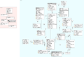
Metamodelling[edit]
The Meta-Object Facility (MOF) is a standard for model-driven engineering. and an metamodel for the Unified Modeling Language.


UML Application[edit]
- Example
-

-
-

-
 Facebook Metamodel
 -
 HBean architecture
 -
 Metamodel Linkedin
 -

-

-

-
-
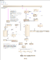 Skos metamodel
 -

-


- Screenshots


