File:Blueprint reading; a practical manual of instruction in blueprint reading through the analysis of typical plates with reference to mechanical drawing conventions and methods, the laws of projection, (14757837716).jpg

From Wikimedia Commons, the free media repository
Jump to navigation Jump to search

Original file(2,448 × 1,814 pixels, file size: 1.17 MB, MIME type: image/jpeg)

Captions

Captions

Add a one-line explanation of what this file represents

Summary

[edit]
Description
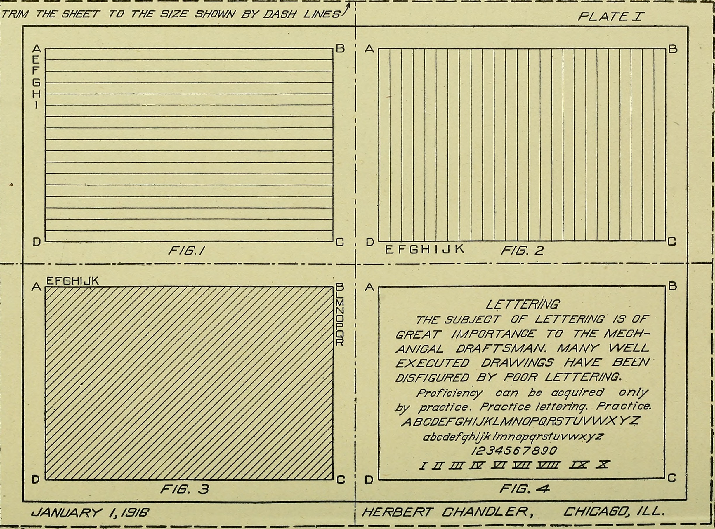
English:

Identifier: blueprintreading00fair (find matches)
Title: Blueprint reading; a practical manual of instruction in blueprint reading through the analysis of typical plates with reference to mechanical drawing conventions and methods, the laws of projection, etc
Year: 1919 (1910s)
Authors: Fairfield, Howard Parker, 1858- Kenison, Ervin Waite, Edward B. (Edward Broughton), 1873- American Technical Society
Subjects: Mechanical drawing Blueprinting
Publisher: Chicago, American technical society
Contributing Library: The Library of Congress
Digitizing Sponsor: The Library of Congress

View Book Page: Book Viewer
About This Book: Catalog Entry
View All Images: All Images From Book
Click here to view book online to see this illustration in context in a browseable online version of this book.

Text Appearing Before Image:
to the pen throughout the operation and stop-ping it sharply at the end of one revolution. Since straight lines canbe more easily drawn tangent to curves than the reverse, it is alwaysadvisable to ink in all arcs or circles first. When a number of circlesare to be drawn from one center, the smaller should be inked first,while the center is in the best possible condition. PLATE I Penciling. To draw Plate I* take a sheet of drawing paper atleast 11 inches by 15 inches and fasten it to the drawing board asalready explained. Find the center of the sheet and draw fine pencillines to represent the lines DE and HK of Fig. 38. Also draw theborder lines L, M, N, and P. Now measure f inch above and below the horizontal center lineand, with the T-square, draw lines through these points. Theselines will form the lower lines DC of Fig. 1 and Fig. 2 and the toplines AB oi Fig. 3 and Fig. 4. Measure ; inch to the right and left *Note Instructions, pages 22 to 25, inclusive. 95 30 MECHANICAL DRAWING
Text Appearing After Image:
96 MECHANICAL DRAWING 31 of the vertical center line; and through these points, draw lines parallelto the center line. These lines should be drawn by placing the triangleon the T-square as shown in Fig. 38. The lines thus drawn, form thesides B C oi Fig. 1 and Fig. 3 and the sides A D oi Fig. 2 and Fig.4.Next draw, with the T-square, the line A B A B A^ inches above thehorizontal center line, and the line D C D C 4f inches below the hori-zontal center line. The rectangles of the four figures may now becompleted by drawing vertical lines 6f inches on each side of thevertical center line; these rectangles are each 6^ inches long and 4^inches wide. Fig. 1. Exercise with Line Pen and T-square. Divide the lineA D into divisions each j inch long, making a fine pencil point orslight puncture at each division such as E, F, G, H, I, etc. Nowplace the T-square with its head at the left-hand edge of the drawingboard and through these points draw light pencil lines extending tothe line B C. In dr

Note About Images

Please note that these images are extracted from scanned page images that may have been digitally enhanced for readability - coloration and appearance of these illustrations may not perfectly resemble the original work.
Date
Source

https://www.flickr.com/photos/internetarchivebookimages/14757837716/

Author Internet Archive Book Images
Permission
(Reusing this file)
At the time of upload, the image license was automatically confirmed using the Flickr API. For more information see Flickr API detail.
Flickr tags
InfoField
Flickr posted date
InfoField
30 July 2014


Licensing

[edit]
This image was taken from Flickr's The Commons. The uploading organization may have various reasons for determining that no known copyright restrictions exist, such as:
  1. The copyright is in the public domain because it has expired;
  2. The copyright was injected into the public domain for other reasons, such as failure to adhere to required formalities or conditions;
  3. The institution owns the copyright but is not interested in exercising control; or
  4. The institution has legal rights sufficient to authorize others to use the work without restrictions.

More information can be found at https://flickr.com/commons/usage/.


Please add additional copyright tags to this image if more specific information about copyright status can be determined. See Commons:Licensing for more information.
This image was originally posted to Flickr by Internet Archive Book Images at https://flickr.com/photos/126377022@N07/14757837716. It was reviewed on 24 September 2015 by FlickreviewR and was confirmed to be licensed under the terms of the No known copyright restrictions.

24 September 2015

File history

Click on a date/time to view the file as it appeared at that time.

Date/TimeThumbnailDimensionsUserComment
current20:07, 28 January 2019Thumbnail for version as of 20:07, 28 January 20192,448 × 1,814 (1.17 MB)SteinsplitterBot (talk | contribs)Bot: Image rotated by 90°
01:19, 24 September 2015Thumbnail for version as of 01:19, 24 September 20151,814 × 2,460 (1.16 MB) (talk | contribs)== {{int:filedesc}} == {{information |description={{en|1=<br> '''Identifier''': blueprintreading00fair ([https://commons.wikimedia.org/w/index.php?title=Special%3ASearch&profile=default&fulltext=Search&search=insource%3A%2Fblueprintreading00fair%2F fin...

There are no pages that use this file.